作者:Damon Tarry, Design Applications Engineer, Same Sky
本 Arduino 示例代碼教程旨在為用戶提供一個堅實的起點,以便通過串行外設接口 (SPI) 通信來配置和讀取 [Same Sky] 的 [AMT22 絕對編碼器] 的數據。該教程將提供所需的硬件和軟件、關鍵設置要求以及單圈和多圈輸出選項的示例代碼包和說明。以下是入門工作所需的物料清單:
- [Arduino 板]
- [AMT22 編碼器]
- [AMT-06C-1-036 電纜] ,或帶有相應連接器的類似電纜
- [Arduino IDE]
- [下載 AMT22 單圈樣例代碼]
- [下載 AMT22 多圈樣例代碼]
AMT22 絕對位置編碼器概覽
Same Sky(前身為 CUI Devices)的 AMT22 是一款絕對編碼器,具有 12 位或 14 位分辨率,即每圈提供精確的唯一位置數。對于 12 位型號來說,這相當于 4,096 個不同的位置,而 14 位型號每轉一圈則有 16,384 個位置。無論旋轉多少次,該器件都會持續報告其絕對位置,準確地向用戶提供精確的器件角度反饋。
該編碼器有單圈和[多圈] 兩種類型。單圈器件測量的是旋轉一圈 360 度過程中的位置,而多圈器件不僅跟蹤旋轉一圈過程中的位置,還跟蹤旋轉整圈的總數。此外,單圈型號還具有可編程零點,使用戶能夠為編碼器的旋轉起點定義參考點。
入門
將編碼器背面的開關調至適當位置,確保器件處于 RUN(運行)模式(圖 1)。現在,按照 [AMT 安裝說明] 將 AMT22 編碼器安裝到電機或組件上,以確保安裝正確。AMT22 支持 9 種不同的軸尺寸,從 2 mm 到 8 mm 不等。
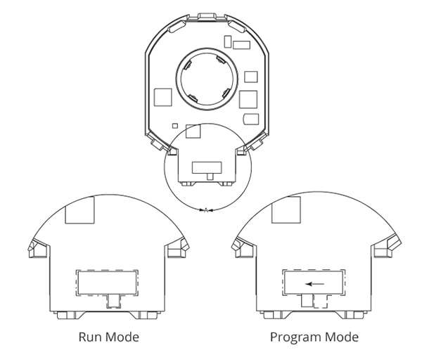 圖 1:將 AMT22 編碼器背面的開關撥至 RUN 模式。(圖片來源:Same Sky)
圖 2 和表 1 中列出的連接專用于 [Arduino Uno 板] ,但所提供的代碼應與大多數 Arduino 板兼容。不過,請注意不同型號的 Arduino 引腳配置可能有所不同。有關其他電路板的準確連接細節,建議參考相應的 Arduino 說明文檔。
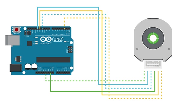 圖 2:Arduino Uno 與 AMT22 編碼器的線路連接。(圖片來源:Same Sky)
| | 功能 | 編碼器引腳數量 | Arduino Uno 引腳 | AMT-DBC-1-036 |
| ------ | ---------------- | ------------------ | --------------- |
| +5 V | 1 | 5 V | 白色/綠色 |
| SCLK | 2 | 13 | 藍色/白色 |
| MOSI | 3 | 11 | 白色/藍色 |
| GND | 4 | GND | 綠色/白色 |
| MISO | 5 | 12 | 橙色/白色 |
| CS | 6 | 2 | 白色/橙色 |
表 1:Arduino Uno 接線的進一步定義。(圖片來源:Same Sky)
當 SPI 通信開始時,AMT22 編碼器立即開始傳輸其絕對位置數據,無需傳統的指令響應結構。在 SPI 傳輸的第一個字節期間,主機發送 0x00,AMT22 同時響應有效位置數據。
如果主機需要發出指令(表 2),例如置零指令,則將在傳輸的第二個字節中發送。這被稱為擴展指令。有關詳細的技術規格,請參閱 AMT22 數據表。
| | 指令 | 字節 | 注意 |
| ---------- | ----------- | ---------- |
| 獲取位置 | 0x00 0x00 | |
| 置零 | 0x00 0x70 | 僅限單圈 |
| 獲得圈數 | 0x00 0xA0 | 僅多圈 |
表 2:已定義的 AMT22 命令。(圖片來源:Same Sky)
代碼教程 - 包含內容和定義
由于 Arduino 的 SPI 總線用于連接 AMT22 編碼器,因此代碼中需要包含 SPI 庫。要將位置數據從 Arduino 發送到計算機,需要使用 Arduino IDE 內置的 USB 串行連接,并在 115200 波特率下進行配置。
此外,還需要定義 AMT22 使用的指令。由于編碼器不處理第一個字節的內容,因此分配了一個 NOP(無操作)來簡化通信過程(列表 1)。
副本
/* Include the SPI library for the arduino boards */
#include < SPI.h >

/* Serial rates for UART */
#define BAUDRATE      115200

/* SPI commands */
#define AMT22_NOP     0x00
#define AMT22_ZERO    0x70
#define AMT22_TURNS   0xA0
列表 1:設置 SPI 接口。
初始化
在 setup() 函數(列表 2)中,首先初始化所有必要的 SPI 引腳并配置串行通信接口。
應初始化串行端口,以便向主計算機傳輸數據。這可以通過把已定義的 BAUDRATE 傳入 Serial.begin() 函數來實現。
啟用 SPI 之前,確保芯片選擇 (CS) 線設置為適當的狀態,以便編碼器做好通信準備。
選擇 SPI 總線與 AMT22 通信的時鐘頻率。對于原型開發而言,盡管 AMT22 支持高達 2 MHz 的時鐘頻率,但 500 kHz 的時鐘頻率還是比較合適的。通過 SPI_CLOCK_DIV32 設置可實現 500 kHz 頻率。假定 Arduino Uno 的時鐘頻率為 16 MHz,這種分頻的結果是 SPI 時鐘頻率為 500 kHz。有關 SPI 時鐘配置的更多詳情,請查閱 Arduino 說明文檔。
配置完成后,可使用 SPI.begin() 對 SPI 總線進行初始化,這將設置三個專用 SPI 引腳:MISO、MOSI 和 SCLK,并使系統做好與編碼器通信的準備。
復制
voidsetup()
{
  uint8_t cs_pin = 2;

  //Set the modes for the SPI CS
  pinMode(cs_pin, OUTPUT);
  //Get the CS line high which is the default inactive state
  digitalWrite(cs_pin, HIGH);

  //Initialize the UART serial connection for debugging
  Serial.begin(BAUDRATE);

  //set the clockrate. Uno clock rate is 16Mhz, divider of 32 gives 500 kHz.
  //500 kHz is a good speed for our test environment
  //SPI.setClockDivider(SPI_CLOCK_DIV2);   // 8 MHz
  //SPI.setClockDivider(SPI_CLOCK_DIV4);   // 4 MHz
  //SPI.setClockDivider(SPI_CLOCK_DIV8);   // 2 MHz
  //SPI.setClockDivider(SPI_CLOCK_DIV16);  // 1 MHz
  SPI.setClockDivider(SPI_CLOCK_DIV32);    // 500 kHz
  //SPI.setClockDivider(SPI_CLOCK_DIV64);  // 250 kHz
  //SPI.setClockDivider(SPI_CLOCK_DIV128); // 125 kHz

  //start SPI bus
  SPI.begin();
}
列表 2:用于初始化所有 SPI 引腳的 setup() 函數。
SPI 通信
與 AMT22 的 SPI 通信通過 Arduino 的 SPI 庫完成,而芯片選擇 (CS) 控制則通過使用數字 I/O 引腳的代碼進行管理。digitalWrite() 函數用于斷言或解除斷言 CS 線路(列表 3)。
AMT22 預計發送兩個 0x00 字節,并在收到這些字節后立即返回數據。由于響應速度快,因此必須遵守 AMT22 規格書中列出的某些最低時序要求。
無論編碼器是 12 位還是 14 位,始終會響應兩個字節(16 位)的數據。上兩位是校驗位,用于驗證數據完整性。對于 12 位版本,下兩位均為 0,返回值必須右移 2 位(或除以 4)才能正常使用。
要獲取位置數據,需要調用 SPI.transfer() 函數,發送 AMT22_NOP 命令。在此過程中,CS 線保持低電平。AMT22 首先發送高字節,因此接收到的字節會左移 8 位,以便與 uint16_t 變量的上半部分對齊。該值將一次性地分配給編碼器位置變量。經過短暫延遲以滿足時序要求后,二次調用 SPI.transfer(),發送另一條 AMT22_NOP 指令。將結果與編碼器位置 (encoderPosition) 中的當前值進行 OR,從而有效地將接收到的兩個字節合并為一個 uint16_t 變量。最后,釋放 CS 線路,完成通信。
復制
uint8_t cs_pin = 2;

//set the CS signal to low
digitalWrite(cs_pin, LOW);
delayMicroseconds(3);

//read the two bytes for position from the encoder, starting with the high byte
uint16_t encoderPosition = SPI.transfer(AMT22_NOP) < < 8; //shift up 8 bits because this is the high byte
delayMicroseconds(3);
encoderPosition |= SPI.transfer(AMT22_NOP); //we do not need a specific command to get the encoder position, just no-op

//set the CS signal to high
digitalWrite(cs_pin, HIGH);
列表 3:設置 SPI 通信。
校驗和驗證
完成 SPI 傳輸后,必須使用校驗和來驗證接收到的數據(列表 4)。
為實現這一驗證,可根據規格書中提供的方程創建一個函數。校驗和包含在接收值的上兩位中,并在位置響應的奇數和偶數位中使用奇校驗。
該函數將執行以下步驟:
- 計算奇數位(1、3、5、7、9、11、13 位的奇偶性
- 計算偶數位(0、2、4、6、8、10、12、14 位)的奇偶性
- 將計算出的奇偶性與校驗位指示的值進行比較
如果校驗和有效,該函數將返回 true,表明數據完整性已得到確認。如果校驗和無效,函數將返回 false,表明接收到的數據可能存在錯誤。
復制
/*
 * Using the equation on the datasheet we can calculate the checksums and then make sure they match what the encoder sent.
 */
boolverifyChecksumSPI(uint16_t message)
{
  //checksum is invert of XOR of bits, so start with 0b11, so things end up inverted
  uint16_t checksum = 0x3;
  for(int i = 0; i < 14; i += 2)
  {
    checksum ^= (message > > i) & 0x3;
  }
  return checksum == (message > > 14);
}
列表 4:驗證校驗和。
數據格式化
如果校驗和驗證確認了數據的完整性,下一步就是刪除上兩位,以更新 encoderPosition 變量(清單 5)。這可以通過對 0x3FFF(或 0b0011111111111111)進行逐位 AND 運算來實現,從而有效保留位置數據的所有 14 個低位。
此外,還需要考慮編碼器的分辨率:12 位還是 14 位。如果分辨率為 12 位,則編碼器位置值必須向右移動 2 位,以適應較低的分辨率。這可確保位置數據在編碼器位置變量中得到準確表達,即根據編碼器的指定分辨率反映編碼器的實際位置。
復制
if (verifyChecksumSPI(encoderPosition)) //position was good
{
  encoderPosition &= 0x3FFF; //discard upper two checksum bits
  if (RESOLUTION == 12) encoderPosition = encoderPosition > > 2; //on a 12-bit encoder, the lower two bits will always be zero

  Serial.print(encoderPosition, DEC); //print the position in decimal format
  Serial.write('n');
}
else//position is bad
{
  Serial.print("Encoder position error.n");
}
列表 5:更新 encoderPosition。
設置零位置(僅限單圈)
AMT22 編碼器的某些型號具有可編程零位功能。要設置該零位,就必須發送一個特定的雙字節指令序列。該過程包括首先發送 AMT22_NOP 指令,然后短暫等待,以滿足 AMT22 規定的最低時序要求。等待之后,發送 AMT22_ZERO 命令,同時確保芯片選擇 (CS) 線被釋放。一旦編碼器收到該指令,就將執行復位操作(列表 6)。
為了避免在復位期間與編碼器通信,可實施 250 ms 延遲,以確保在編碼器通電期間不會向其發送任何指令。
雖然利用代碼可在開始運行時設置編碼器零位,但在典型應用中,更常見的做法是在系統內使用器件的初始配置過程中只設置一次零位。這種做法有助于在編碼器的整個運行壽命期間保持其位置反饋的完整性。
復制
/*
 * The AMT22 bus allows for extended commands. The first byte is 0x00 like a normal position transfer,
 * but the second byte is the command.
 * This function takes the pin number of the desired device as an input
 */
voidsetZeroSPI(uint8_t cs_pin)
{
  //set CS to low
  digitalWrite(cs_pin, LOW);
  delayMicroseconds(3);

  //send the first byte of the command
  SPI.transfer(AMT22_NOP);
  delayMicroseconds(3);

  //send the second byte of the command
  SPI.transfer(AMT22_ZERO);
  delayMicroseconds(3);

  //set CS to high
  digitalWrite(cs_pin, HIGH);

  delay(250); //250 millisecond delay to allow the encoder to reset
}
列表 6:設置單圈 AMT22 編碼器的零位。
圈數讀取計數器(限多圈)
AMT22 編碼器的某些型號支持多圈計數器,允許用戶在單數據檢索序列中讀取位置和圈數。
如果接收到的位置數據無效,系統應將錯誤通知用戶。相反,如果位置有效,程序應以十進制格式報告位置(列表 7)。這一功能增強了編碼器功能,可全面地反饋絕對位置和完整的圈數,從而在需要精確旋轉數據的應用中實現更精確的監測和控制。
復制
uint8_t cs_pin = 2;

//set the CS signal to low
digitalWrite(cs_pin, LOW);
delayMicroseconds(3);

//read the two bytes for position from the encoder, starting with the high byte
uint16_t encoderPosition = SPI.transfer(AMT22_NOP) < < 8; //shift up 8 bits because this is the high byte
delayMicroseconds(3);
encoderPosition |= SPI.transfer(AMT22_TURNS); //we send the turns command (0xA0) here, to tell the encoder to send us the turns count after the position

//wait 40us before reading the turns counter
delayMicroseconds(40);

//read the two bytes for turns from the encoder, starting with the high byte
uint16_t encoderTurns = SPI.transfer(AMT22_NOP) < < 8; //shift up 8 bits because this is the high byte
delayMicroseconds(3);
encoderTurns |= SPI.transfer(AMT22_NOP);
delayMicroseconds(3);

//set the CS signal to high
digitalWrite(cs_pin, HIGH);
列表 7:AMT22 多圈讀取編碼器中的編碼器位置和圈數計數器。
運行代碼
代碼創建成功后,就可以將其上傳到 Arduino 并與 AMT22 編碼器建立通信。
要監控輸出,請打開 Arduino IDE 中的串行監控器,并確保將數據速率設置為 115200 波特。這樣,用戶就可以觀察編碼器的運行情況,并實時查看位置報告數據。串行監控器啟動后,編碼器應開始傳輸位置信息,顯示其在系統中的功能(圖 3)。
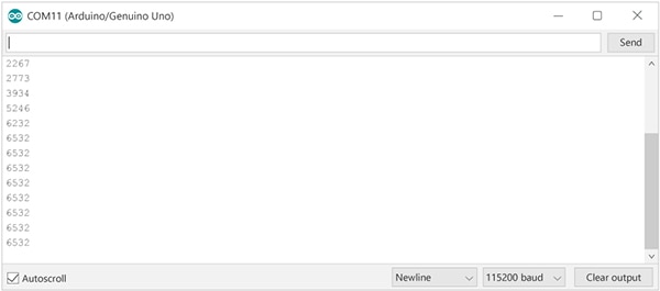 圖 3:Arduino 收到的編碼器報告的位置(圖片來源:Same Sky)
多個編碼器
能夠與同一總線上的多個編碼器進行通信,是使用 SPI 器件的一大優勢。為此,需要為每個編碼器分配一個額外數字 I/O 引腳,以實現單獨的芯片選擇 (CS) 控制。
在示例代碼(列表 8)中,利用 CS 引腳陣列支持任意數量的編碼器。這種設計實現了可擴展通信,使用戶能夠根據需要輕松地添加更多的編碼器。通過修改功能以接受與所需器件相對應的引腳編號,使用代碼能以動態方式控制 SPI 總線上哪個編碼器處于活動狀態,從而確保能獨立地訪問和操作每個器件。
復制
uint8_t cs_pins[] = {2}; //only one encoder connected, using pin 2 on arduino for CS
//uint8_t cs_pins[] = {2, 3}; //two encoders connected, using pins 2 & 3 on arduino for CS
列表 8:設置讀取多個編碼器陣列。
下一步是循環讀取陣列中的每個 CS 引腳,并從每個連接的編碼器中讀取位置。這樣,通過斷言每個編碼器的芯片選擇線,執行 SPI 傳輸并檢索位置數據,系統就可以激活每個編碼器。代碼將依次選擇每個編碼器,執行 SPI 通信并釋放 CS 線,以確保所有連接的器件都能查詢到其位置信息(列表 9)。
復制
voidloop()
{
  for(int encoder = 0; encoder < sizeof(cs_pins); ++encoder)
  {
    uint8_t cs_pin = cs_pins[encoder];

    //set the CS signal to low
    digitalWrite(cs_pin, LOW);
    delayMicroseconds(3);

    //read the two bytes for position from the encoder, starting with the high byte
    uint16_t encoderPosition = SPI.transfer(AMT22_NOP) < < 8; //shift up 8 bits because this is the high byte
    delayMicroseconds(3);
    encoderPosition |= SPI.transfer(AMT22_NOP); //we do not need a specific command to get the encoder position, just no-op

    //set the CS signal to high
    digitalWrite(cs_pin, HIGH);

    if (verifyChecksumSPI(encoderPosition)) //position was good, print to serial stream
    {
      encoderPosition &= 0x3FFF; //discard upper two checksum bits
      if (RESOLUTION == 12) encoderPosition = encoderPosition > > 2; //on a 12-bit encoder, the lower two bits will always be zero

      Serial.print("Encoder #");
      Serial.print(encoder, DEC);
      Serial.print(" position: ");
      Serial.print(encoderPosition, DEC); //print the position in decimal format
      Serial.write('n');
    }
    else//position is bad, let the user know how many times we tried
    {
      Serial.print("Encoder #");
      Serial.print(encoder, DEC);
      Serial.print(" position error.n");
    }
  }

  //For the purpose of this demo we don't need the position returned that quickly so let's wait a half second between reads
  //delay() is in milliseconds
  delay(500);
}
列表 9:從多個編碼器讀取編碼器位置變量。
數據傳輸結束后,在釋放芯片選擇線之前需要極短的等待時間。根據規格書,這個極短的時間為 3 ms。雖然這種延遲通常是在較慢的數據傳輸速率下自然觀察到的,但好的做法是在代碼中明確實現這種延遲,以確保正常運行并遵守時序規范。這就確保了與 AMT22 編碼器的可靠通信。
結束語
用戶現在應該對配置和讀取 Same Sky AMT22 絕對編碼器的數據有了基本了解。本文重點介紹了 AMT22 絕對編碼器。Same Sky 還擁有一系列 [AMT 模塊化編碼器] ,包括增量式、絕對式和換向式版本。
審核編輯 黃宇
-
編碼器
+關注
關注
45文章
3664瀏覽量
135098 -
SPI
+關注
關注
17文章
1721瀏覽量
91998 -
代碼
+關注
關注
30文章
4823瀏覽量
68920 -
絕對編碼器
+關注
關注
0文章
14瀏覽量
6987 -
Arduino
+關注
關注
188文章
6477瀏覽量
187646
發布評論請先 登錄
相關推薦


 用于 SPI 絕對編碼器的 Arduino 示例代碼



評論