?CW32學(xué)習(xí)開發(fā)筆記
?
硬件原理圖:
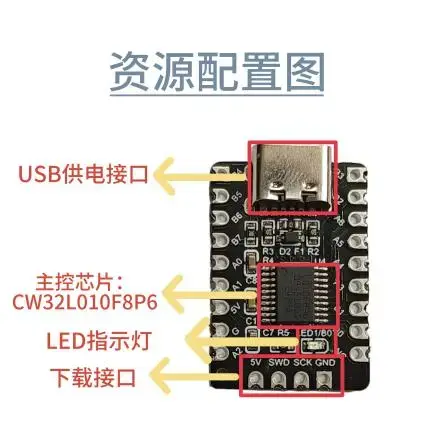
主芯片
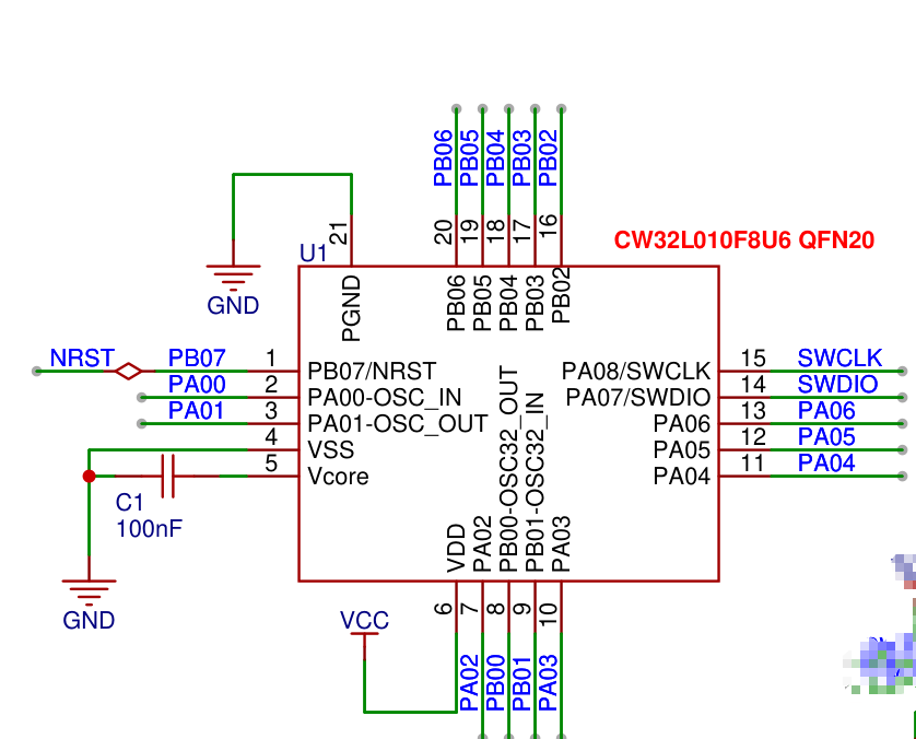
引腳封裝圖:
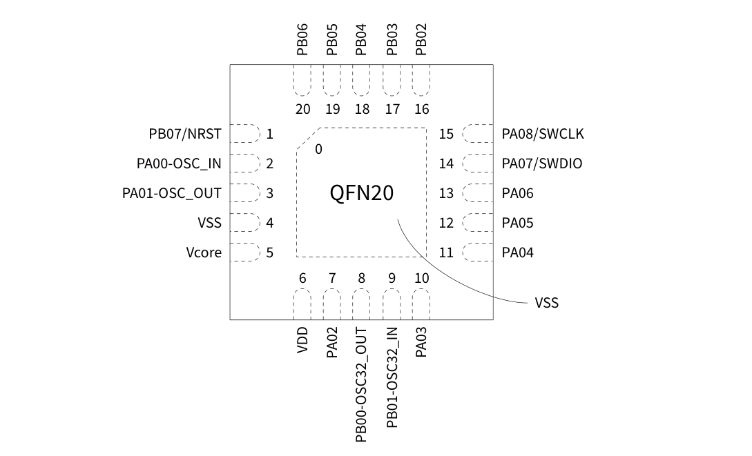
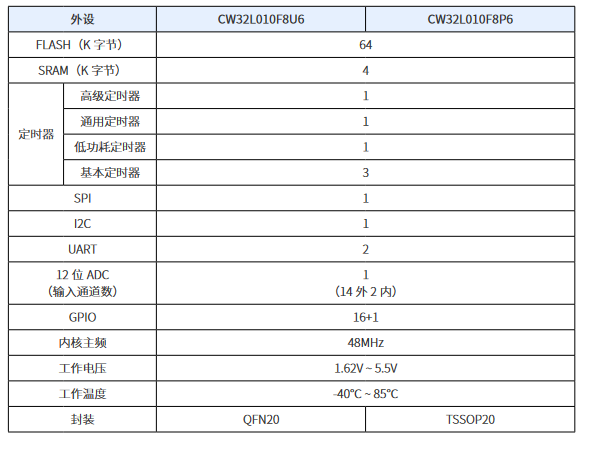
** CW32L010 是基于 eFlash 的單芯片低功耗微控制器,集成了主頻高達(dá) 48MHz 的 ARM? Cortex?-M0+ 內(nèi)核、**
高速嵌入式存儲(chǔ)器(多至 64K 字節(jié) FLASH 和多至 4K 字節(jié) SRAM)以及一系列全面的增強(qiáng)型外設(shè)和 I/O 口。
所有型號(hào)都提供全套的通信接口(二路 UART、一路 SPI 和一路 I2C)、12 位高速 ADC、四組通用和基本定時(shí)器、
一組低功耗定時(shí)器以及一組高級(jí)控制 PWM 定時(shí)器。
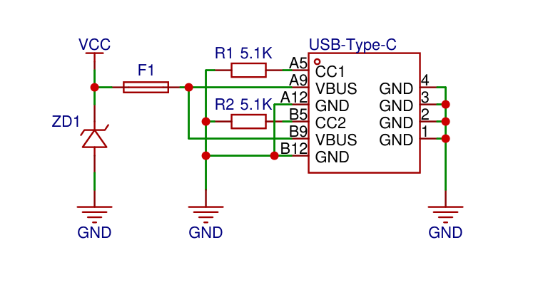
供電電源
** 使用type-c直接供電即可,不需要再接其他電源轉(zhuǎn)換芯片,CW32L010 可以在 -40℃到 85℃的溫度范圍內(nèi)工作,供電電壓寬達(dá) 1.62V ~ 5.5V。支持 Sleep 和 DeepSleep兩種低功耗工作模式。**
復(fù)位電路
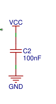
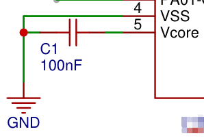
濾波電路
內(nèi)部穩(wěn)壓

調(diào)試下載
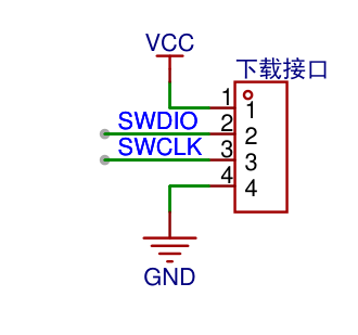
默認(rèn)使用SWD接口下載程序,原理圖如下:
板載指示燈
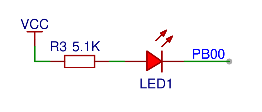
用于查看系統(tǒng)運(yùn)行狀態(tài),原理圖如下:
軟件功能
工程創(chuàng)建
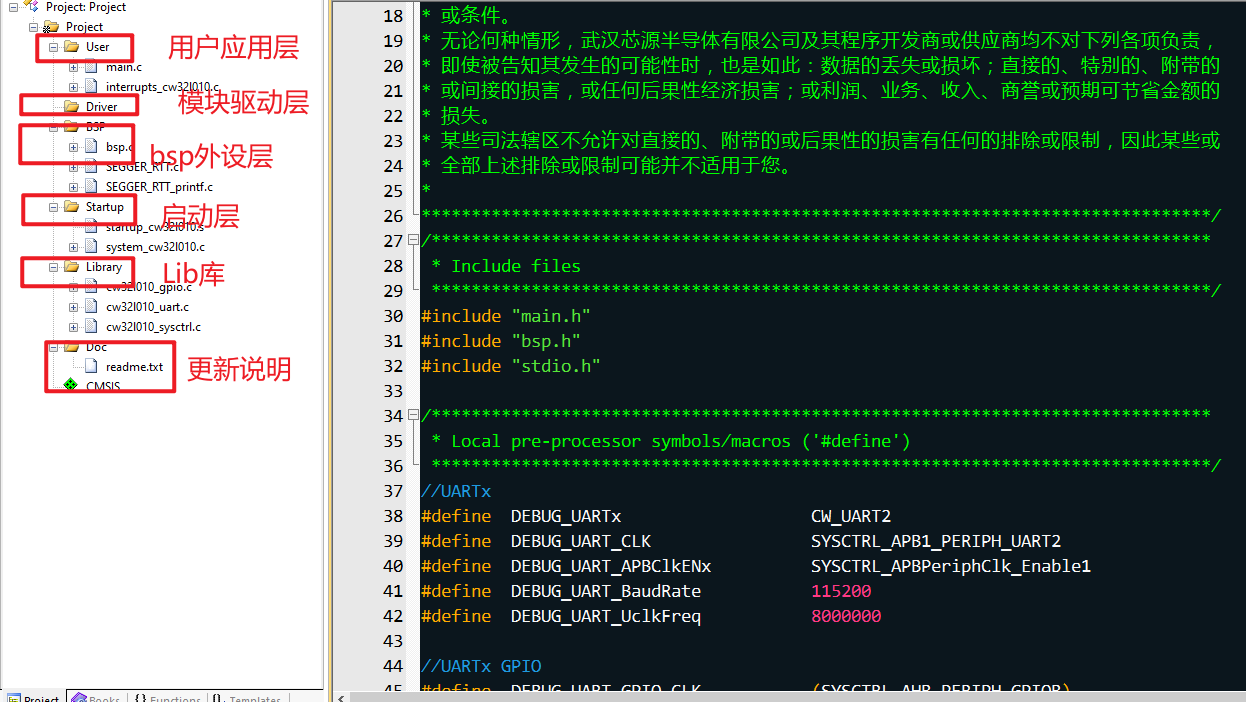
具體如何創(chuàng)建工程就不所說明了,官方例程都有說明,我主要說下的我的目錄結(jié)構(gòu)設(shè)計(jì):
串口通訊
** 內(nèi)部集成 2 個(gè)通用異步收發(fā)器 (UART),支持異步全雙工、同步半雙工和單線半雙工模式,支持硬件數(shù)據(jù)流控**
和多機(jī)通信,還支持 LIN(局域互連網(wǎng)絡(luò));可編程數(shù)據(jù)幀結(jié)構(gòu),可以通過小數(shù)波特率發(fā)生器提供寬范圍的
波特率選擇。內(nèi)置定時(shí)器模塊,支持等待超時(shí)檢測(cè)、接收空閑檢測(cè)、自動(dòng)波特率檢測(cè)和通用定時(shí)功能。
UART 控制器工作在雙時(shí)鐘域下,允許在深度休眠模式下進(jìn)行數(shù)據(jù)的接收,接收完成中斷可以喚醒 MCU 回到
運(yùn)行模式。注意:僅 UART1 支持 LIN 和定時(shí)器功能;UART2 可通過片內(nèi)外設(shè)互聯(lián)與 BTIM/GTIM/ATIM 的從模式協(xié)同工
作實(shí)現(xiàn)超時(shí)定時(shí)器相關(guān)功能。我們接著實(shí)現(xiàn)串口通訊功能;
- 1.串口功能硬件引腳

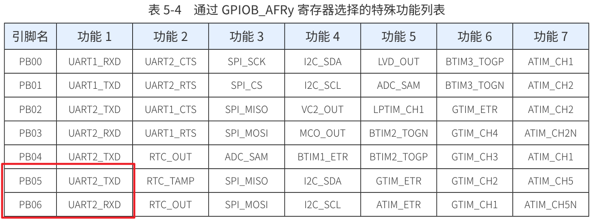
使用串口2來是實(shí)現(xiàn)通訊,再看引腳的復(fù)用功能。
- 2.代碼實(shí)現(xiàn)
#include  "bsp_uart2.h"
 #include "cw32l010_gpio.h"
 #include "cw32l010_uart.h"
 #include  "stdio.h"
 #include "cw32l010_sysctrl.h"
 ?
 //UARTx
 #define  DEBUG_UARTx                   CW_UART2
 #define  DEBUG_UART_CLK                SYSCTRL_APB1_PERIPH_UART2
 #define  DEBUG_UART_APBClkENx          SYSCTRL_APBPeriphClk_Enable1
 #define  DEBUG_UART_BaudRate           115200
 #define  DEBUG_UART_UclkFreq           HSIOSC_VALUE     //串口全速運(yùn)行
 ?
 //UARTx GPIO
 #define  DEBUG_UART_GPIO_CLK           (SYSCTRL_AHB_PERIPH_GPIOB)
 #define  DEBUG_UART_TX_GPIO_PORT       CW_GPIOB
 #define  DEBUG_UART_TX_GPIO_PIN        GPIO_PIN_5
 #define  DEBUG_UART_RX_GPIO_PORT       CW_GPIOB
 #define  DEBUG_UART_RX_GPIO_PIN        GPIO_PIN_6
 ?
 //GPIO AF
 #define  DEBUG_UART_AFTX               PB05_AFx_UART2TXD()
 #define  DEBUG_UART_AFRX               PB06_AFx_UART2RXD()
 ?
 ?
 static void UART_Configuration(void)
 {
 //    //外設(shè)時(shí)鐘使能,放在外設(shè)里面自己進(jìn)行使能

     DEBUG_UART_APBClkENx(DEBUG_UART_CLK, ENABLE);


 UART_InitTypeDef UART_InitStructure = {0};
 ?
     UART_InitStructure.UART_BaudRate = DEBUG_UART_BaudRate;
     UART_InitStructure.UART_Over = UART_Over_16;
     UART_InitStructure.UART_Source = UART_Source_PCLK;
     UART_InitStructure.UART_UclkFreq = DEBUG_UART_UclkFreq;
     UART_InitStructure.UART_StartBit = UART_StartBit_FE;
     UART_InitStructure.UART_StopBits = UART_StopBits_1;
     UART_InitStructure.UART_Parity = UART_Parity_No ;
     UART_InitStructure.UART_HardwareFlowControl = UART_HardwareFlowControl_None;
     UART_InitStructure.UART_Mode = UART_Mode_Rx | UART_Mode_Tx;
     UART_Init(DEBUG_UARTx, &UART_InitStructure);
 ?
 }
 ?
 ?
 /**
  * @brief 配置GPIO
  *
  */
 static void GPIO_Configuration(void)
 {
     GPIO_InitTypeDef GPIO_InitStructure = {0};

 //外設(shè)時(shí)鐘使能,放在外設(shè)里面自己進(jìn)行使能
 SYSCTRL_AHBPeriphClk_Enable(DEBUG_UART_GPIO_CLK, ENABLE);

     GPIO_WritePin(DEBUG_UART_TX_GPIO_PORT, DEBUG_UART_TX_GPIO_PIN,GPIO_Pin_SET);    // 設(shè)置TXD的默認(rèn)電平為高,空閑
 ?
     GPIO_InitStructure.Pins = DEBUG_UART_TX_GPIO_PIN;
     GPIO_InitStructure.Mode = GPIO_MODE_OUTPUT_PP;
     GPIO_Init(DEBUG_UART_TX_GPIO_PORT, &GPIO_InitStructure);
 ?
     GPIO_InitStructure.Pins = DEBUG_UART_RX_GPIO_PIN;
     GPIO_InitStructure.Mode = GPIO_MODE_INPUT_PULLUP;
     GPIO_Init(DEBUG_UART_RX_GPIO_PORT, &GPIO_InitStructure);
 ?
      //UART TX RX 復(fù)用
     DEBUG_UART_AFTX;
     DEBUG_UART_AFRX;
 }
 ?
 ?
 ?
 void UART2_Configuration(void)
 {
 UART_Configuration();
 GPIO_Configuration();
 }
 ?
 ?
 #ifdef __GNUC__
     /* With GCC/RAISONANCE, small printf (option LD Linker- >Libraries- >Small printf
     set to 'Yes') calls __io_putchar() */
     #define PUTCHAR_PROTOTYPE int __io_putchar(int ch)
 #else
     #define PUTCHAR_PROTOTYPE int fputc(int ch, FILE *f)
 #endif /* __GNUC__ */
 ?
 ?
 /**
  * @brief Retargets the C library printf function to the UART.
  *
  */
 PUTCHAR_PROTOTYPE
 {
     UART_SendData_8bit(DEBUG_UARTx, (uint8_t)ch);
 ?
     while (UART_GetFlagStatus(DEBUG_UARTx, UART_FLAG_TXE) == RESET);
 ?
     return ch;
 }
 ?
 size_t __write(int handle, const unsigned char * buffer, size_t size)
 {
     size_t nChars = 0;
 ?
     if (buffer == 0)
     {
         /*
          * This means that we should flush internal buffers.  Since we
          * don't we just return.  (Remember, "handle" == -1 means that all
          * handles should be flushed.)
          */
         return 0;
     }
 ?
 ?
     for (/* Empty */; size != 0; --size)
     {
         UART_SendData_8bit(DEBUG_UARTx, *buffer++);
         while (UART_GetFlagStatus(DEBUG_UARTx, UART_FLAG_TXE) == RESET);
         ++nChars;
     }
 ?
     return nChars;
 }
 ?
 /******************************************************************************
  * EOF (not truncated)
  ******************************************************************************/
 #ifdef  USE_FULL_ASSERT
 /**
   * @brief  Reports the name of the source file and the source line number
   *         where the assert_param error has occurred.
   * @param  file: pointer to the source file name
   * @param  line: assert_param error line source number
   * @retval None
   */
 void assert_failed(uint8_t *file, uint32_t line)
 {
     /* USER CODE BEGIN 6 */
     /* User can add his own implementation to report the file name and line number,
        tex: printf("Wrong parameters value: file %s on line %drn", file, line) */
     /* USER CODE END 6 */
 }
 #endif /* USE_FULL_ASSERT */
 ?
- 3.編寫打印測(cè)試函數(shù)
static void Printf_Function(void)
 {
     DEBUG_LOG("rn");
     DEBUG_LOG("  Compile time:");
     DEBUG_LOG(__DATE__);
     DEBUG_LOG("  ");
     DEBUG_LOG(__TIME__);
     DEBUG_LOG("rn+-------------------+rn");
     DEBUG_LOG("%s,%s,%d,%srn", __FUNCTION__,__FILE__,__LINE__,__DATE__);
     DEBUG_LOG("rn+-------------------+rn");
 }
- 4.查看串口終端信息
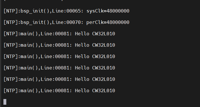
使用MobaXterm終端工具查看:
- 5.注意點(diǎn)
為了讓代碼支持GNU擴(kuò)展,keil設(shè)置需要注意:
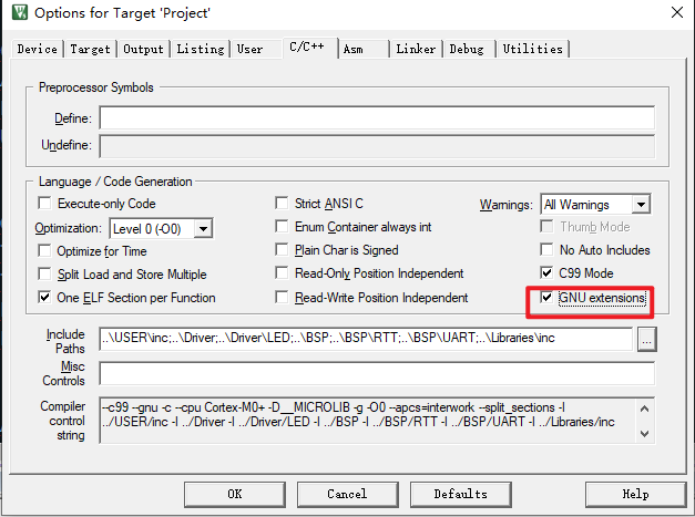
同時(shí),串口打印的時(shí)候,添加頭文件"stdio.h";
GPIO口輸入輸出
根據(jù)板載資源,使用板載的LED來測(cè)試。前面硬件說明的時(shí)候提到,使用的引腳為PB00;就直接上代碼了。
- 1.編寫驅(qū)動(dòng)代碼
#include  "drv_led.h"
 ?
 ?
 ?
 ?
 // 初始化 LED 引腳
 void LED_Init(void)
 {
     GPIO_InitTypeDef GPIO_InitStruct = {0};
 ?
     __SYSCTRL_GPIOB_CLK_ENABLE();
 ?
     GPIO_InitStruct.IT = GPIO_IT_NONE;
     GPIO_InitStruct.Mode = GPIO_MODE_OUTPUT_PP;
     GPIO_InitStruct.Pins = LED_GPIO_PINS;
 ?
     GPIO_Init(LED_GPIO_PORT, &GPIO_InitStruct);

 }
 ?
 // 控制 LED 開關(guān)
 void LED_Control(GPIO_PinState state)
 {
 GPIO_WritePin(LED_GPIO_PORT, LED_GPIO_PINS,state);
 }
 ?
 // 切換 LED 狀態(tài)
 void LED_Toggle(void) {
     GPIO_TogglePin(LED_GPIO_PORT, LED_GPIO_PINS);
 }
 ?
 // 讀取 LED 狀態(tài)
 int LED_Read(void) {
     return GPIO_ReadPin(LED_GPIO_PORT, LED_GPIO_PINS) == GPIO_Pin_SET ? 1 : 0;
 }
 ?
 // 定義并初始化 LED 操作結(jié)構(gòu)體實(shí)例
 LED_Ops_t myLED = {
     .init = LED_Init,
     .control = LED_Control,
     .toggle = LED_Toggle,
     .read = LED_Read
 };
 ?
- 2.編寫測(cè)試程序
int32_t main(void)
 {

 bsp_init();
 driver_init();
 ?
     while(1)
     {
 SysTickDelay(1000);
 myLED.toggle();
     }
 }
調(diào)試下載之后,可直接觀察板載LED燈是否在循環(huán)閃爍。
調(diào)試等級(jí)
- 1.直接上代碼,調(diào)試等級(jí)頭文件;
#ifndef __LOG_H
 #define __LOG_H
 #include < stdio.h >
 #include < stdlib.h >
 #include < string.h >
 #include < stdarg.h >
 #define GLOB_LOG_EVEL           LOG_DEBUG
 ?
 typedef enum {
     FALSE,
     TRUE
     } status;
 // 定義日志級(jí)別
 typedef enum {
     LOG_DEBUG,
     LOG_INFO,
     LOG_WARNING,
     LOG_ERROR
     } LogLevel;
 ?
 ?
 ?
 //extern LogMsg lmsg;
 // 顏色
 #define Blue    "?33[34m" // Blue
 #define Green   "?33[32m" // Green
 #define Yellow  "?33[33m" // Yellow
 #define Red     "?33[31m" // Red
 #define Reset   "?33[0m"  // Reset color
 ?
 ?
 // 記錄日志的宏定義
 ?
 #define LOG_MESSAGE(format, ...) printf("[NTP]:%s(),Line:%05d: " format "rn", __FUNCTION__, __LINE__, ##__VA_ARGS__)
 ?
 void LOG_MSG(LogLevel level, const char *message);
 #endif
 ?
- 2.功能函數(shù)實(shí)現(xiàn)文件:
#include "log.h"
 ?
 // 日志輸出函數(shù)
 void LOG_MSG(LogLevel level, const char *message) {
     switch (level) {
         case LOG_DEBUG:
             printf(Blue "DEBUG: %s" Reset "rn", message);
             break;
         case LOG_INFO:
             printf(Green "INFO: %s" Reset "rn", message);
             break;
         case LOG_WARNING:
             printf(Yellow "WARNING: %s" Reset "rn", message);
             break;
         case LOG_ERROR:
             printf(Red "ERROR: %s" Reset "rn", message);
             break;
         default:
             printf("UNKNOWN: %sn", message);
             break;
     }
 }
- 3.編寫測(cè)試函數(shù)
/*宏定義錯(cuò)誤碼信息*/
 static void Error_Code_Info(void)
 {
 DEBUG_LOG("%d", SYSTEM_OK);
 DEBUG_LOG("%d", SYSTEM_ERR_E_1);
 DEBUG_LOG("%d", SYSTEM_ERR_E_2);
 DEBUG_LOG("%d", SYSTEM_ERR_MQTT_INFO_ERROR);
 ?
 ?
 LOG_MSG(LOG_DEBUG, "This is a debug message");
 LOG_MSG(LOG_INFO, "This is an info message");
 LOG_MSG(LOG_WARNING, "This is a warning message");
 LOG_MSG(LOG_ERROR, "This is an error message");
 }
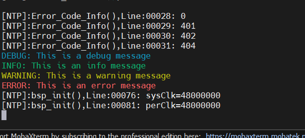
- 4.終端輸出
串口中斷
CW32單片機(jī)的串口有好幾種工作方式,異步全雙工,同步半雙工,單線半雙工,由于沒有DMA通道,為了避免頻繁的進(jìn)入中斷,采用串口接收中斷,串口查詢發(fā)送方式實(shí)現(xiàn)收發(fā);
配置簡(jiǎn)單隊(duì)列消息,實(shí)現(xiàn)方式如下:
- 1、定義隊(duì)列結(jié)構(gòu)
#define myQ2_SIZE     512
 #define RxBuffer2_SIZE   myQ2_SIZE
 ?
 typedef volatile struct
 {
     uint8_t     m_getIdx;
     uint8_t     m_putIdx;
     uint8_t     m_entry[ myQ2_SIZE ];
 } myQ2;
 ?
 extern  myQ2   volatile RxBuffer2;
 extern  myQ2   volatile TxBuffer2;
 ?
 void  UART2_Buffer_Init(void);
- 2、初始化隊(duì)列結(jié)構(gòu)
myQ2   volatile RxBuffer2;
 myQ2   volatile TxBuffer2;
 ?
 ?
 void  UART2_Buffer_Init(void)
 {
     CBUF_Init(RxBuffer2);
     CBUF_Init(TxBuffer2);
 }
 ?
- 3、使能串口接收中斷
void NVIC_Configuration(void)
 {
     //優(yōu)先級(jí),無優(yōu)先級(jí)分組
     NVIC_SetPriority(DEBUG_UART_IRQ, 0);
     //UARTx中斷使能
     NVIC_EnableIRQ(DEBUG_UART_IRQ);


 //使能UARTx RC中斷
     UART_ITConfig(DEBUG_UARTx, UART_IT_RC, ENABLE);
 UART_ClearITPendingBit(CW_UART2, UART_IT_RC);

 }
- 4、編寫測(cè)試函數(shù),實(shí)現(xiàn)串口功能收發(fā)
int32_t main(void)
 {
 bsp_init();
 driver_init();
     while(1)
     {
 uint16_t  dataLen=0;
 dataLen = CBUF_Len(RxBuffer2);
 if(dataLen!=0)
 {
 //拷貝數(shù)據(jù)
 memcpy((char*)TxBuffer2.m_entry,(char*)RxBuffer2.m_entry,dataLen);
 //查詢發(fā)送數(shù)據(jù)
 UART_SendBuf_Polling(CW_UART2,TxBuffer2.m_entry,dataLen);

 USART2_Clear();
 }
 SysTickDelay(1000);
 myLED.toggle();
     }
 }
- 5、查看串口終端收發(fā)
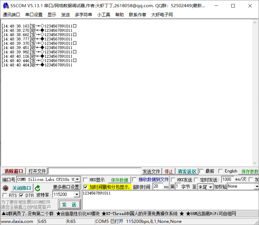
從截圖可以看出,當(dāng)前收發(fā)數(shù)據(jù)一致;
控制臺(tái)Shell
下面介紹下開源項(xiàng)目是 letter-shell,一個(gè)功能強(qiáng)大的嵌入式shell,letter shell 3.x是一個(gè)C語言編寫的,可以嵌入在程序中的嵌入式shell,通俗一點(diǎn)說就是一個(gè)串口命令行,可以通過命令行調(diào)用、運(yùn)行程序中的函數(shù)。目前 letter-shell 3.0版本支持的功能有:
- 命令自動(dòng)補(bǔ)全
- 快捷鍵功能定義
- 命令權(quán)限管理
- 用戶管理
- 變量支持
項(xiàng)目地址: [https://github.com/NevermindZZT/letter-shell]
移植過程:
- 1.復(fù)制源碼到工程中:
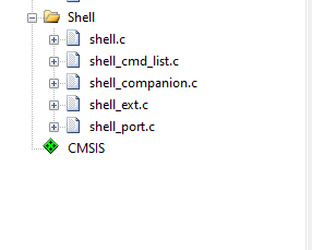
- 2.在自定義接口
shell_port.c中實(shí)現(xiàn)自己的串口讀寫函數(shù)
#include "shell.h"
 #include "main.h"
 #include "bsp_uart2.h"
 #include "shell_port.h"
 ?
 Shell shell;
 char shellBuffer[512];
 ?
 ?
 /**
  * @brief 用戶shell寫
  *
  * @param data 數(shù)據(jù)
  * @param len 數(shù)據(jù)長(zhǎng)度
  *
  * @return short 實(shí)際寫入的數(shù)據(jù)長(zhǎng)度
  */
 short userShellWrite(char *data, unsigned short len)
 {
 UART_SendBuf_Polling(CW_UART2,(uint8_t *)data, len);
     return len;
 }
 ?
 ?
 /**
  * @brief 用戶shell讀
  *
  * @param data 數(shù)據(jù)
  * @param len 數(shù)據(jù)長(zhǎng)度
  *
  * @return short 實(shí)際讀取到
  */
 short userShellRead(char *data, unsigned short len)
 {
 return UART2_GetString((uint8_t *)data, len);
 }
 ?
 /**
  * @brief 用戶shell上鎖
  *
  * @param shell shell
  *
  * @return int 0
  */
 int userShellLock(Shell *shell)
 {
 return 0;
 }
 ?
 /**
  * @brief 用戶shell解鎖
  *
  * @param shell shell
  *
  * @return int 0
  */
 int userShellUnlock(Shell *shell)
 {
 return 0;
 }
 ?
 /**
  * @brief 用戶shell初始化
  *
  */
 void userShellInit(void)
 {
 ?
 //注冊(cè)自己實(shí)現(xiàn)的寫函數(shù)
     shell.write = userShellWrite;
 //shell.read = userShellRead;
 //調(diào)用shell初始化函數(shù)
     shellInit(&shell, shellBuffer, 512);

 }
- 3.在終端函數(shù)中定義
對(duì)于裸機(jī)環(huán)境,在主循環(huán)中調(diào)用shellTask,或者在接收到數(shù)據(jù)時(shí),調(diào)用shellHandler,我這里在中斷中調(diào)用
void UART2_IRQHandler(void)
 {
     /* USER CODE BEGIN */
     uint8_t TxRxBuffer;
     if (UART_GetITStatus(CW_UART2, UART_IT_RC) != RESET)
     {
 /*使用簡(jiǎn)易隊(duì)列進(jìn)行接收數(shù)據(jù)*/
 TxRxBuffer = UART_ReceiveData_8bit(CW_UART2);
 shellHandler(&shell,TxRxBuffer);
         CBUF_Push(RxBuffer2, TxRxBuffer);
         UART_ClearITPendingBit(CW_UART2, UART_IT_RC);
     }
     /* USER CODE END */
 }
- 4.調(diào)用初始化shell
userShellInit();
- 5.串口終端實(shí)現(xiàn)結(jié)果
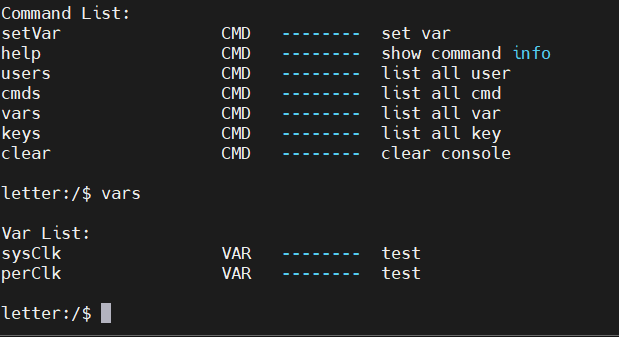
查看當(dāng)前系統(tǒng)時(shí)鐘:
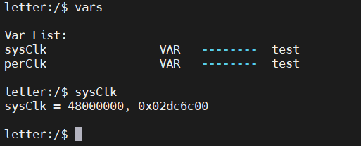
其他實(shí)現(xiàn)方式,參考官方文檔說明。
審核編輯 黃宇
-
芯片
+關(guān)注
關(guān)注
455文章
50844瀏覽量
423845 -
CW32
+關(guān)注
關(guān)注
1文章
210瀏覽量
655
發(fā)布評(píng)論請(qǐng)先 登錄
相關(guān)推薦
基于CW32L010單片機(jī)的低成本電動(dòng)工具方案
【產(chǎn)品方案】基于CW32L010低成本電動(dòng)工具方案
【產(chǎn)品方案】基于CW32L010的低成本USB充電檢測(cè)儀產(chǎn)品方案
CW32L010安全低功耗MCU,樹立M0+產(chǎn)品行業(yè)新標(biāo)桿!
【CW32L010 Mini Board 測(cè)評(píng)】簡(jiǎn)介、點(diǎn)燈
方案介紹|CW32L010安全低功耗MCU:驅(qū)動(dòng)高速風(fēng)筒新力量
CW32L010demo
CW32L010安全低功耗MCU,樹立M0+產(chǎn)品行業(yè)新標(biāo)桿!

CW32L0100核心板的使用體驗(yàn)
CW32L010 新品初體驗(yàn)
基于CW32L010F8P6的電機(jī)驅(qū)動(dòng)板簡(jiǎn)易測(cè)試
CW32L010低成本工業(yè)儀表介紹

【產(chǎn)品方案】CW32L010低成本工業(yè)儀表(方案組成框圖、硬件原理圖)
關(guān)于CW32L010電動(dòng)工具控制板中SWD下載口占用時(shí)的下載解決方法

CW32L010 Motor Control Driver無刷電機(jī)驅(qū)動(dòng)板上手體驗(yàn)


 CW32L010學(xué)習(xí)筆記


評(píng)論