一、PSS仿真設置
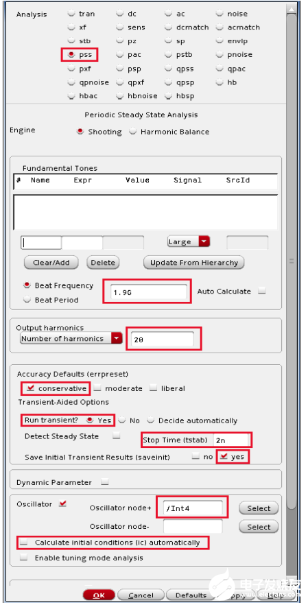
1、Beat Frequency振蕩器的近似頻率
2、Number of harmonics是單邊諧波分析的諧波個數
3、tstab通常設置為時鐘周期的2-3倍。不過tstab應該設置的足夠長,保證振蕩器達到穩定狀態。這里2有點小,我設置為周期的20倍
4、Oscillator node,單端輸出選一個即可,差分輸出選兩個節點。
注:如果仿真提示不收斂,可以在Simulation->Convergence Aids->initial Condition設置輸出節點的初始電壓,一個gnd,一個vdd
二、hb和hbnoise仿真設置
首先是hb仿真設置
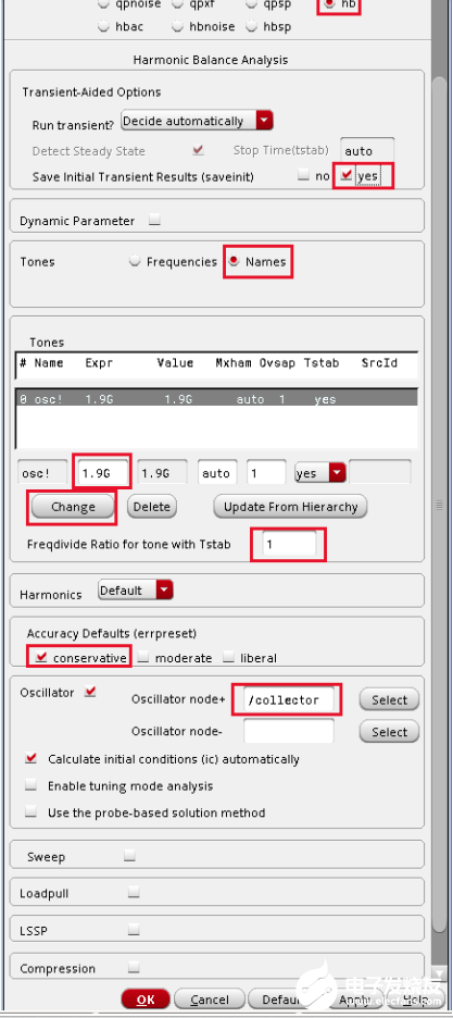
1、首先選擇Oscillator Section,添加輸出端口,彈出窗口直接關閉即可
2、在Tones section選擇osc!行
3、填寫預估振蕩頻率和過采樣選擇1(正弦波選擇1的過采樣最合適)
4、Freqdivide比例設置為1表示沒有分頻器,即分頻比為1
然后是hbnoise仿真設置
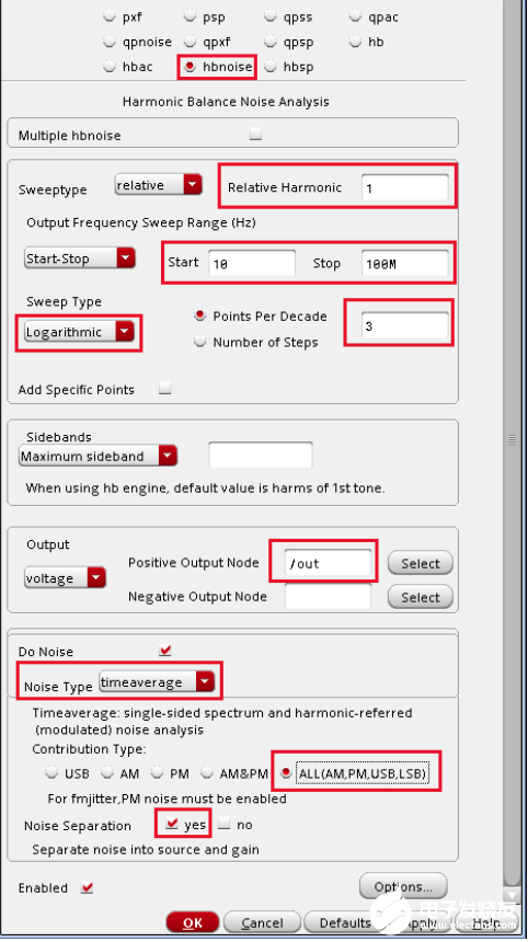
參數設置說明如下:
Type 1 in the Relative Harmonic field. You are trying to determine the noise associated with the fundamental frequency of the oscillator.
Type 10 in the Start Field in the Output Frequency Sweep Range (Hz) section.
Type 100M in the Stop Field in the Output Frequency Sweep Range (Hz) section.Set the frequency sweep range as appropriate for your circuit (or application).
Set the Sweep Type to Logarithmic.
Type 3 in the Points Per Decade field. Typically, 3 to 5 points per decade are a reasonable number to capture the noise behavior of the circuit.
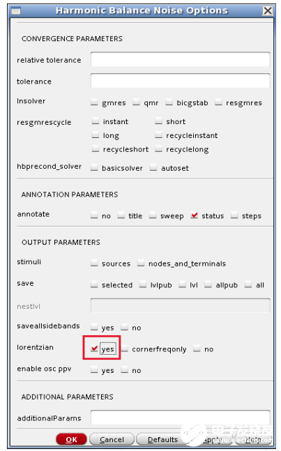
此外,為了看到低頻時的相噪水平,需要在hbnoise option設置lorentzian option to yes.
hbnoise仿真完成后
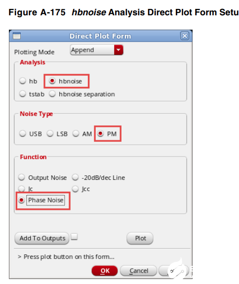
使用Direct Plot Form畫出總的相位噪聲曲線
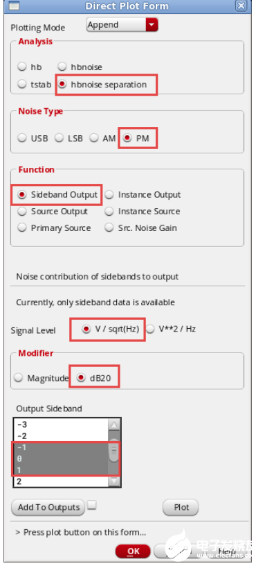
同樣使用Direct Plot Form,分別畫出各個-1,0和1輸出邊帶的噪聲貢獻:
This will plot the noise contribution of the -1, 0, and 1 sidebands to the output. This allows the identification of which noise frequencies are causing the largest noise contribution at he output of the circuit.
找到最大噪聲貢獻的邊帶為-1邊帶之后,仿真-1邊帶各個元件的噪聲大小
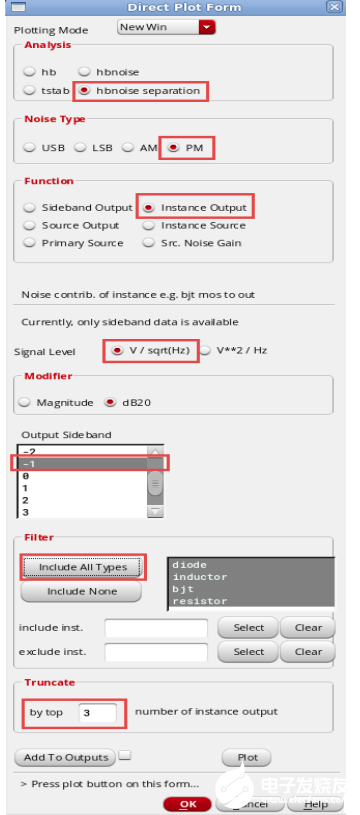
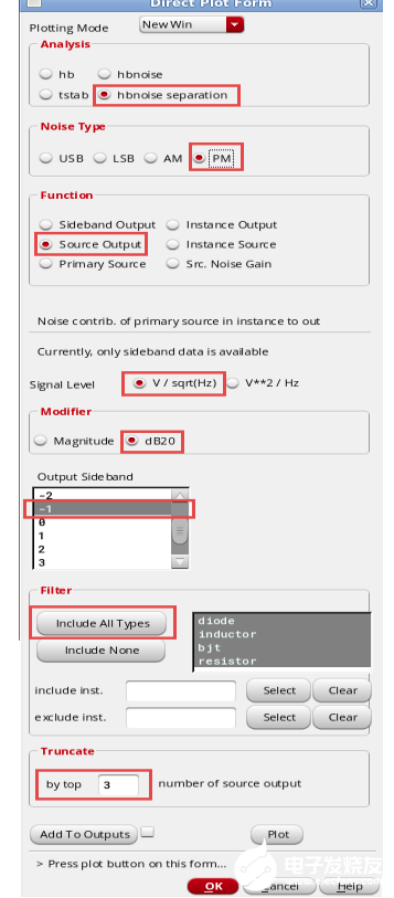
為了清楚得看到噪聲源對輸出得影響,
同樣的設置,勾選source output查看噪聲源對輸出噪聲貢獻最大的前三名
最后在Results->print可以打印在某個頻偏得各個器件噪聲對輸出噪聲的貢獻比。
審核編輯:黃飛
-
振蕩器
+關注
關注
28文章
3845瀏覽量
139267 -
諧波
+關注
關注
7文章
830瀏覽量
41853 -
分頻器
+關注
關注
43文章
447瀏覽量
50028 -
相位噪聲
+關注
關注
2文章
181瀏覽量
22901
發布評論請先 登錄
相關推薦
20M低相位噪聲晶體振蕩器的設計

振蕩器相位噪聲到時間抖動的轉換


 振蕩器的相位噪聲仿真設置


評論