設計思想
設計一個交流信號的檢測裝置,對輸入進行前期處理,經過 A/D 采樣后數模轉換,將測量結果顯示出來,并具有一定的測量輔助及擴展功能。設計分別采用了 LM324 運算放大器進行信號放大,把被測輸入正弦波信號最小幅度為有效值 10 毫伏,頻率為 100HZ~10KHZ 的正弦信號通過兩級放大,放大成接近 2 伏但不超過 2 伏的正弦信號。
然后,分為兩支。一支接 LM2903 比較器以地為零點進行過零比較,輸出數字信號接相應的 FPGA 用以測量頻率。另一支接峰值保持電路用來保證采樣到波形的最大值,再接數模轉換器轉換成模擬量通過門電路轉換輸入到相應的 FPGA 用以測量峰值,再配合用 VHDL 語言編的采用可編程邏輯器件完成數字電路的功能的程序。基本就可以較完整的實現題目要求了。
工作原理與功能
增益帶寬積
運放的增益是隨信號的頻率變化而變化的。即輸入信號的頻率增大,其增益將逐漸減小,然而,其增益與其帶寬的乘積是一個常數。所謂運放的帶寬是指其輸出電壓隨信號源頻率的增大而使其下降到最大值的 0.707 倍時的頻率范圍。增益帶寬積這個參數表述了某一型號運放在高增益下必然降低帶寬,高帶寬必然降低增益的特性。
這種情況下運放的帶寬增益積也只是個理論值。由于運放輸入端參數、反饋電阻、輸入電阻、PCB 分布參數,運放對頻率響應的變化,使運放電路在輸入信號頻率沒有達到數據手冊中標識的增益帶寬積時,提前衰減到輸入信號的 0.707 倍。再者,由多次諧波造成的輸出電壓幅度大于正常的輸出電壓幅度。還要考慮到壓擺率對輸出信號造成的失真。所以,實際應用中帶寬增益積不能達到資料手冊中的給出參數。這是在設計中應該注意的。所以選擇運放的帶寬增益積參數要高于運放實際帶寬增益積的十倍比較合適。
比較器的作用
比較器是將一個模擬電壓信號與一個基準電壓相比較的電路。常用的幅度比較電路有電壓幅度比較器,具有遲滯特性的比較器。這些比較器的閾值是固定的,有的只有一個閾值,有的具有兩個閾值。我們選擇如下圖的電路,過零比較,把正弦信號轉化成方波信號,以便 FPGA 可以通過計數器測量頻率。
A/D 我們按照手冊中的基本電路圖編寫,并為了測得穩定的峰值,在 A/D 的輸入端我們加入了峰值保持電路(如下圖),目的是能夠使采樣采到峰值并繼續保持下去。在 A/D 輸出端,我們考慮到由于 FPGA 輸入端只有 3.3V,所以在 A/D 的輸入端我們加入八進八出的 74HC244N,目的是使 A/D 輸出的 5V 可以轉換到 FPGA 的 3.3V,防止 FPGA 燒壞。
硬件電路圖
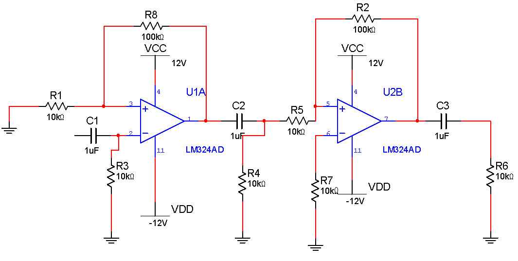
兩級LM324運算放大器電路圖
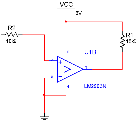
LM2903比較器電路圖
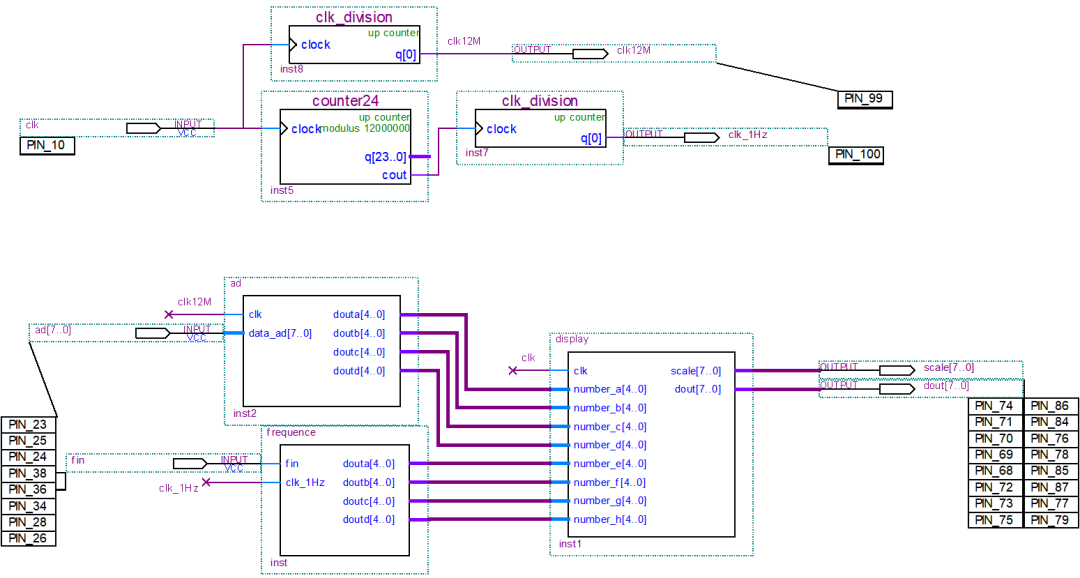
FPGA電路圖
系統框圖
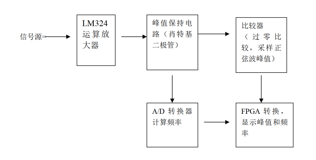
利用ABB PLC 軟件編寫程序
數模轉換器
library IEEE;
use IEEE.std_logic_1164.all;
use IEEE.std_logic_unsigned.all;


entity ad is
  PORT(
    clk                            : in      std_logic;
    data_ad                        : in      std_logic_vector(7 downto 0);
    douta,doutb,doutc,doutd        : out     std_logic_vector(4 downto 0)
    );
end;


ARCHITECTURE behave of ad is


  TYPE STATE_TYPE IS (s0,s1,s2,s3,s4,s5,s6,s7,s8);
  signal state: STATE_TYPE;


    signal a,b,c,d              : std_logic_vector(9 downto 0);
    signal dis_a,dis_b          : std_logic_vector(4 downto 0);
    signal dis_c,dis_d          : std_logic_vector(4 downto 0);
    signal data_transf_buff     : std_logic_vector(10 downto 0);

begin


-------------------------------------


process (clk,state)
  begin
    if clk 'event and clk ='1' then
      case state is

    when s0 = >
        data_transf_buff<="00000000000";
        a(7 downto 0)<=data_ad;
            state<=s1;
        when s1 = >
        b(7 downto 0)<=data_ad;
            state<=s2;
    when s2 = >
            c(7 downto 0)<=data_ad;
            state<=s3;
        when s3 = >
            d<= data_ad + a + b + c;

            state<=s4;
-----------------------------------------------------------------
                when s4 = >
            dis_a <= "00000"; dis_b <= "00000";
            dis_c <= "00000"; dis_d <= "00000";
            data_transf_buff(10 downto 1)<=d;
                    state<=s5;


        when s5 = >
            if data_transf_buff >= "01111101000" then
                  data_transf_buff <= data_transf_buff - "01111101000";
                  dis_a <= dis_a + 1;
                  state<=s5;
            else
                  state<=s6;
            end if;

        when s6 = >
            if data_transf_buff >= "00001100100" then
                  data_transf_buff <= data_transf_buff - "00001100100";
                  dis_b <= dis_b + 1;
                  state<=s6;
            else
                  state<=s7;
            end if;

        when s7 = >
            if data_transf_buff >= "00000001010" then
                  data_transf_buff <= data_transf_buff - "00000001010";
                  dis_c <= dis_c + 1;
                  state<=s7;
            else
                  dis_d <= data_transf_buff(4 downto 0);
                  state<=s8;
            end if;
        when s8 = >
            douta <= dis_a;  doutb <= dis_b;
            doutc <= dis_c;  doutd <= dis_d;
                    state <= s0;

       end case;
    end if;
end process;


end behave;
調頻
library IEEE;
use IEEE.std_logic_1164.all;
use IEEE.std_logic_unsigned.all;


entity frequence is
  port(
       fin         : in  std_logic;
       clk_1Hz     : in  std_logic;
       douta       : out std_logic_vector(4 downto 0);
       doutb       : out std_logic_vector(4 downto 0);
       doutc       : out std_logic_vector(4 downto 0);
       doutd       : out std_logic_vector(4 downto 0)
      );
end;


architecture behav of frequence is


signal clk_half                          : std_logic;
signal r_1,r_2,r_3,r_4,r_5               : std_logic_vector(4 downto 0);
signal t_1,t_2,t_3,t_4,t_5               : std_logic_vector(4 downto 0);


begin
   process(clk_1Hz)
     begin
       if rising_edge(clk_1Hz) then
            clk_half<=NOT clk_half;
       end if;

   end process;

   process(fin,clk_half)
    begin
     if rising_edge(fin) then
         if clk_half='1' then r_1<=r_1+1;
                              if r_1 >"01001" then r_1<="00000"; r_2<=r_2+1; end if;
                              if r_2 >"01001" then r_2<="00000"; r_3<=r_3+1; end if;
                              if r_3 >"01001" then r_3<="00000"; r_4<=r_4+1; end if;
                              if r_4 >"01001" then r_4<="00000"; r_5<=r_5+1; end if;
                              if r_5 >"01001" then r_1<="01001"; r_2<="01001"; r_3<="01001";
                                                  r_4<="01001"; r_5<="01001"; end if;
         elsif clk_half='0'  then
                  r_1<="00000";r_2<="00000";r_3<="00000";r_4<="00000";r_5<="00000";
         end if;
     end if;
    end process;

  process(clk_half)
     begin
      if falling_edge(clk_half) then
          t_1<=r_1;   t_3<=r_3;  t_5<=r_5;
          t_2<=r_2;   t_4<=r_4;
      end if;
   end process;
-------------------------------------------------------------------------------------------


process(t_1,t_2,t_3,t_4,t_5)
  begin
    if t_5="00000" then


    if t_4="00000" then douta<="11111";
        else douta<=t_4; end if;


        if t_3="00000" then doutb<="11111";
        else doutb<=t_3; end if;


        if t_2="00000" then doutc<="11111";
        else doutc<=t_2; end if;

        doutd<=t_1;


    else  doutd<=t_2;doutc<=t_3;
          doutb<=t_4+"10000";
          douta<=t_5;
    end if;
end process;
end;
計數器
LIBRARY ieee;
USE ieee.std_logic_1164.all;


LIBRARY lpm;
USE lpm.all;


ENTITY counter24 IS
  PORT
  (
    clock    : IN STD_LOGIC ;
    cout    : OUT STD_LOGIC ;
    q    : OUT STD_LOGIC_VECTOR (23 DOWNTO 0)
  );
END counter24;


ARCHITECTURE SYN OF counter24 IS


  SIGNAL sub_wire0  : STD_LOGIC ;
  SIGNAL sub_wire1  : STD_LOGIC_VECTOR (23 DOWNTO 0);


  COMPONENT lpm_counter
  GENERIC (
    lpm_direction    : STRING;
    lpm_modulus    : NATURAL;
    lpm_port_updown    : STRING;
    lpm_type    : STRING;
    lpm_width    : NATURAL
  );
  PORT (
      clock  : IN STD_LOGIC ;
      cout  : OUT STD_LOGIC ;
      q  : OUT STD_LOGIC_VECTOR (23 DOWNTO 0)
  );
  END COMPONENT;


BEGIN
  cout    <= sub_wire0;
  q    <= sub_wire1(23 DOWNTO 0);


  lpm_counter_component : lpm_counter
  GENERIC MAP (
    lpm_direction = > "UP",
    lpm_modulus = > 12000000,
    lpm_port_updown = > "PORT_UNUSED",
    lpm_type = > "LPM_COUNTER",
    lpm_width = > 24
  )
  PORT MAP (
    clock = > clock,
    cout = > sub_wire0,
    q = > sub_wire1
  );
END SYN;
顯示
library IEEE;
use IEEE.std_logic_1164.all;
use IEEE.std_logic_unsigned.all;


entity display is
  port(clk       : in  std_logic;
       number_a  : in  std_logic_vector(4 downto 0);
       number_b  : in  std_logic_vector(4 downto 0);
       number_c  : in  std_logic_vector(4 downto 0);
       number_d  : in  std_logic_vector(4 downto 0);
       number_e  : in  std_logic_vector(4 downto 0);
       number_f  : in  std_logic_vector(4 downto 0);
       number_g  : in  std_logic_vector(4 downto 0);
       number_h  : in  std_logic_vector(4 downto 0);
       scale     : out std_logic_vector(7 downto 0);
       dout      : out std_logic_vector(7 downto 0)
             );
end;


architecture behav of display is


signal number     :  std_logic_vector(2 downto 0);
signal LED        :  std_logic_vector(4 downto 0);
signal clk_counter:  std_logic_vector(5 downto 0);
signal clk_d      :  std_logic;


begin


process(clk)
     begin
       if rising_edge(clk) then
          clk_counter<=clk_counter+1;
          if clk_counter=0 then
                 clk_d<=not clk_d;
          end if;
       end if;
end process;

process(clk_d)
    begin
       if rising_edge(clk_d) then
            number<=number+1;
            case number(2 downto 0) is
              when "000" = > LED<=number_a; scale<="00000001";
              when "001" = > LED<=number_b; scale<="00000010";
              when "010" = > LED<=number_c; scale<="00000100";
              when "011" = > LED<=number_d; scale<="00001000";
              when "100" = > LED<=number_e; scale<="00010000";
              when "101" = > LED<=number_f; scale<="00100000";
              when "110" = > LED<=number_g; scale<="01000000";
              when "111" = > LED<=number_h; scale<="10000000";
              when others = > scale<="00000000";
            end case;
        end if;
end process;


process(LED)
    begin
       case LED(4 downto 0) is
            when "00000" = > dout <= "11000000";
            when "00001" = > dout <= "11111001";
            when "00010" = > dout <= "10100100";
            when "00011" = > dout <= "10110000";
            when "00100" = > dout <= "10011001";
            when "00101" = > dout <= "10010010";
            when "00110" = > dout <= "10000010";
            when "00111" = > dout <= "11111000";
             when "01000" = > dout <= "10000000";
           when "01001" = > dout <= "10010000";


      when "10000" = > dout <= "01000000";
            when "10001" = > dout <= "01111001";
            when "10010" = > dout <= "00100100";
            when "10011" = > dout <= "00110000";
            when "10100" = > dout <= "00011001";
            when "10101" = > dout <= "00010010";
            when "10110" = > dout <= "00000010";
            when "10111" = > dout <= "01111000";
             when "11000" = > dout <= "00000000";
           when "11001" = > dout <= "00010000";


           when "11111" = > dout <= "11111111";
           when others = > dout <= "11111111";
        end case;
end process;


end;
06
特色成果
本組在運算放大器的設計中,充分考慮到被測輸入正弦波信號最小幅度為有效值 10 毫伏,而放大后輸入到數模轉換器的電壓不能超過 2 伏而要無限接近于 2 伏。所以,在設計時,我們采用兩級放大,第一級放大 10 倍,第二級根據輸入信號的不同由一個小開關控制。當輸入信號為 1015mv 時,采用 13 倍放大,當輸入信號為 1620mv 時,采用 10 倍放大。這樣,可以根據信號的峰值不同采用不同的放大級數,有利于信號的放大不是真。
-
運放電路
+關注
關注
38文章
361瀏覽量
34940 -
比較器
+關注
關注
14文章
1658瀏覽量
107352 -
LM324
+關注
關注
15文章
166瀏覽量
65194 -
數模轉換器
+關注
關注
14文章
1021瀏覽量
83296 -
FPGA芯片
+關注
關注
3文章
246瀏覽量
39837
發布評論請先 登錄
相關推薦
可編程邏輯器件
PLD可編程邏輯器件
可編程邏輯器件基礎及應用實驗指導書
什么是PLD(可編程邏輯器件)


 怎樣設計一個基于可編程邏輯器件的信號檢測裝置?



評論