Introduction
In the past, much has been written about SCSI bus system performance. However, very little information has been provided to new users regarding the physical bus connections. This application note begins at the system level and proceeds down to the actual pin-level connections. It provides the new SCSI user with the kind of detail necessary connect the DS2119M in a typical wide-bus application.SCSI Network Applications
Figure 1 illustrates a typical SCSI network application. It demonstrates the variety of devices that can be connected to the SCSI bus. The workstation acts as the main controller. Thus, the HBA (host bus adapter) card has on-board SCSI termination; it resides within the workstation enclosure and is connected to the computer motherboard. The SCSI hub provides the end of the bus termination and branches out to another SCSI network through three or more ports.
Figure 1. Typical SCSI network application.
In this configuration, however, it is not obvious that small subsystems can be connected to a shared network bus. For example, in the case of the RAID (redundant array of independent disks) drive, there may be multiple SCSI drives connected in the RAID enclosure. This RAID enclosure provides its own SCSI termination. The same is true of the server subsystem.
Figure 2 offers a closer look at a disk subsystem. As previously stated, the HBA card is connected to the motherboard. Figure 2 illustrates the daisy-chained connection from the HBA to n+ disks. Up to 16 devices, including the HBA card, can be connected to a single SCSI bus in Ultra3 and other wide-bus applications.

Figure 2. Typical SCSI disk drive system.
The diagram also shows termination on the HBA card and on the SCSI cable. Therefore, only two terminators are required - one at the beginning of the bus on the HBA and the other at the end of the cable. In some cases, termination can be connected to the last disk drive in lieu of terminating the cable. However, under no circumstances should both the disk drive and the cable be terminated. Additional termination could impede system performance and possibly cause a marginal loss of data integrity.
The DS2119M is a 9-line LVD/SE SCSI terminator IC that provides the proper impedance levels for both single-ended (SE) and low-voltage differential (LVD) signals. Therefore, 9 lines are used in SE mode and 9 pairs are used in LVD mode to provide the proper line impedance.
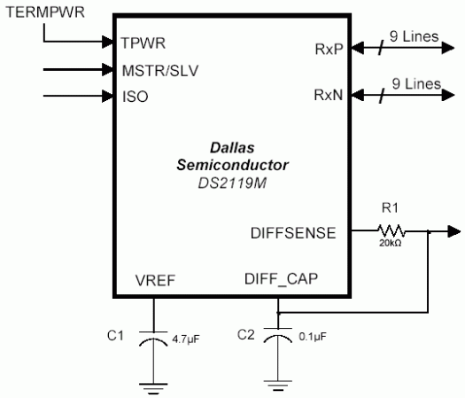
Figure 3. DS2119M Ultra3 LVD/SE multimode SCSI terminator.
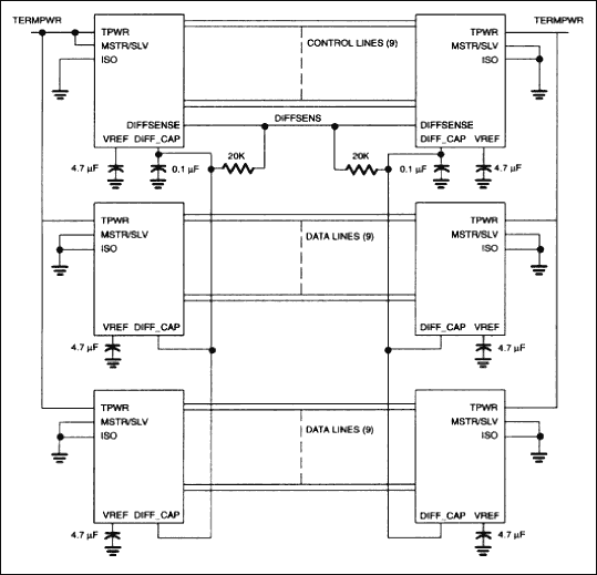
In a typical application the SCSI devices are daisy-chained, as shown in Figure 4. The DIFF_CAP signal monitors the DIFFSENS line to determine the proper operating mode of the device. The DIFFSENSE pin can also drive the SCSI DIFFSENS line (when MSTR/SLV = 1) to determine the SCSI bus operating mode. The DS2119M combines LVD and SE termination with DIFFSENS sourcing and detection.
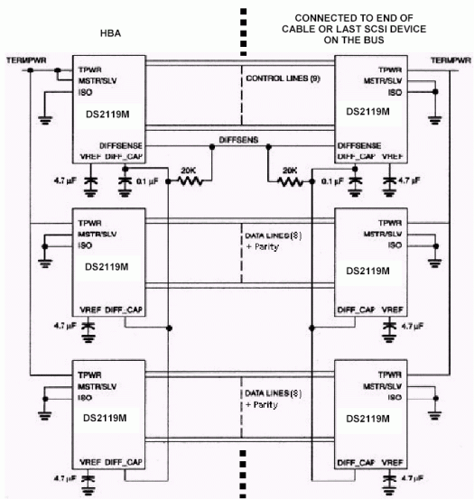
Figure 4. DS2119M SCSI bus connections.
A bandgap reference is fed into two amplifiers, which creates a 1.25V reference voltage in LVD mode and a 2.85V reference voltage in SE mode. That same control logic switches in/out parallel resistors to change the total termination resistance accordingly. In SE mode the RxP pins are switched to ground.
The DIFFSENSE circuitry decodes trinary logic. There is one of three voltages on the SCSI DIFFSENS control line. If the voltage is below 0.6V, SE mode is selected. If DIFFSENS is above 2.15V, HVD mode selection causes the DS2119M to isolate itself from the bus. If the DIFFSENS line is between 0.6 V and 2.15V, LVD mode is selected. The ISO input pin, as shown in Figure 4, can be pulled high by the HBA to isolate all the devices from the bus.
Figure 5 illustrates a complete wire diagram of the SCSI wide-bus application. The diagram shows an end-of-the bus application connected to the 68-pin P-type connector. Since each end of the wide-bus requires three DS2119M SCSI terminators, six devices are needed to terminate the path, as shown in Figure 4. Please note that there is one device selected on each end of the bus as the master. When the MSTR/SLV pin is pulled high, the DIFFSENSE pin outputd the appropriate mode level to be detected by the DIFF_CAP pins.
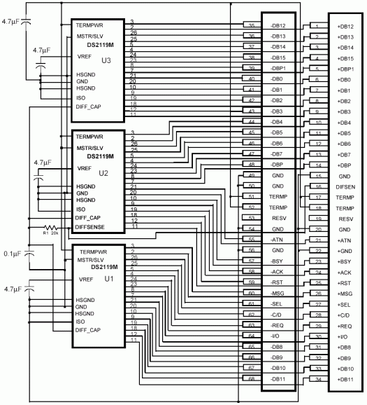
Figure 5. Typical SCSI bus pin connections.
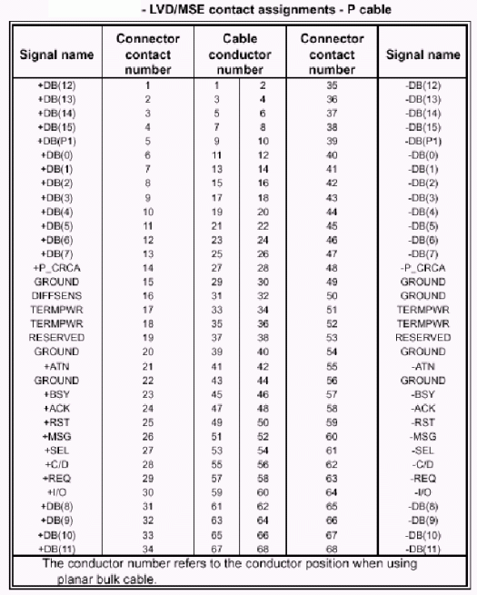
Appendix A: LVD/SE Contact Assignments - P Cable
 電子發(fā)燒友App






評論