 電子發燒友App


 創作
創作 發文章
發文章 發帖
發帖  提問
提問  發資料
發資料 發視頻
發視頻資料介紹
描述
大家好,歡迎回來,這是我的 Neko Punk Synth Version 2,它是以貓為主題的合成器,由 Arduino Nano 和 Mozzi 庫提供支持。
?
通過改變 5 個滑動罐的位置,Mozzi 可以產生更加復雜和有趣的咆哮、掃動和合唱聲音。這些聲音可以通過熟悉的合成單元(如振蕩器、延遲和濾波器)快速輕松地構建。
我幾周前制作的 Previous 版本是基于最初的 Atari Punk Console,最初是由Forrest Mims在1980 年制作的。它使用觸發單穩態設置的非穩態多諧振蕩器設置。通過組合這兩個設置,我們得到一個步進音發生器或一個 atari 朋克合成器。
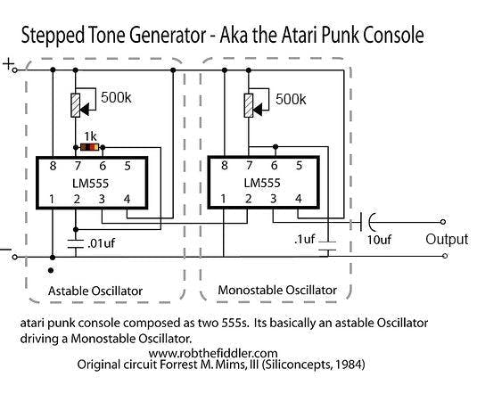
這很容易做,但我對它的結果不滿意。
一年前,我用 Mozzi Library 制作了一個類似的合成器,效果非常好,所以我想為什么不在 Neko Punk Synth 的 V2 中使用 Mozzi,為了讓事情變得超級酷,我使用了滑動罐,讓這個合成器具有了賽博朋克的感覺——看起來。
所需材料
這些是這個建筑中使用的東西-
阿杜諾納米
由PCBWAY提供的定制PCB
鋰離子 5V 升壓模塊
3.7V 鋰離子電池
3D 打印外殼
4歐喇叭
滑塊盆
V2 PCB 可能是我做過的最簡單的電路板。
它使用 Arduino Nano 作為基礎微控制器,五個滑塊盆與 Arduino nano 連接。
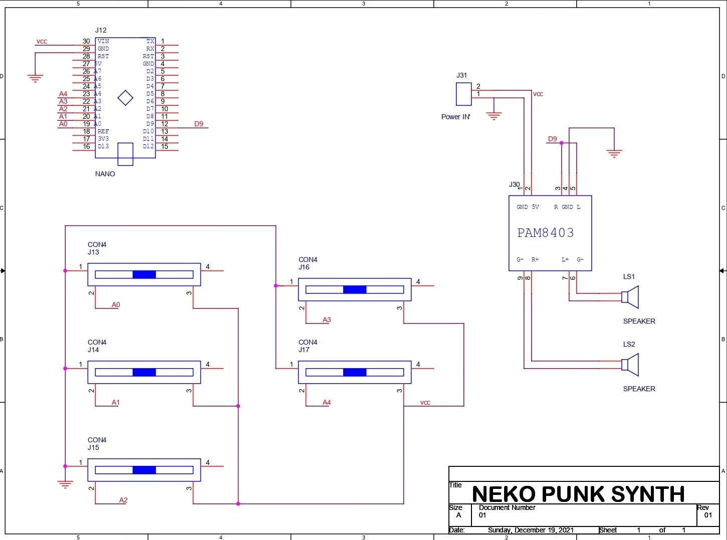
D9 進入 PAM8403 音頻放大器模塊的輸入端,PAM8403 的輸出端與兩個 CON2 引腳相連,因此我們可以用它添加揚聲器。
整個設置需要 5V 才能工作。
要為這個設置供電,我必須使用你可以在網上找到的這個鋰離子電池升壓模塊,這些模塊非常便宜而且工作得很好。
1 / 2
它將 3.7V 的鋰離子電池升壓至恒定的 5V 1A 或 2A,以便我們的 MCU 設置正常工作。
我在我的 OrCad PCB 套件中準備了 PCB,并添加了一些圖形以增加電路板的美感。
從 PCBWAY 獲取電路板
我在這個項目中使用了 PCBWAY PCB 服務。我在PCBWAY的報價頁面上傳了這個項目的Gerber文件。
對于這個 Synth 板,我選擇了白色阻焊層顏色,因為我在板的頂部添加了很多圓形圖形和自定義藝術。
黑色絲印搭配白色阻焊顏色看起來很棒。
我在一周內收到了 PCB,PCB 質量非常好,這個 PCB 很大,我喜歡這些 PCB 的質量沒有因為尺寸而受到影響。
印刷電路板組裝
現在這塊板沒有任何 SMD Componenets 所以我們只需要手動將所有東西放在這塊板上并用烙鐵焊接它們。
我首先收集所有材料并開始使用滑動電位器進行組裝。
然后我將所有的 Pot 從頂部放在它們的位置,并從 PCB 的底部焊接它們的焊盤。
在此之后,我在它們的位置添加了 Arduino Nano 和 PAM8403 模塊,組裝就差不多完成了。
上傳代碼
這是基于 Mozzi 庫的項目的主要草圖。
?
/* Example using 2 light dependent resistors (LDRs) to change FM synthesis parameters, and a knob for fundamental frequency, using Mozzi sonification library. Demonstrates analog input, audio and control oscillators, phase modulation and smoothing a control signal at audio rate to avoid clicks. Also demonstrates AutoMap, which maps unpredictable inputs to a set range. This example goes with a tutorial on the Mozzi site: http://sensorium.github.io/Mozzi/learn/Mozzi_Introductory_Tutorial.pdf The circuit: Audio output on digital pin 9 (on a Uno or similar), or check the README or http://sensorium.github.com/Mozzi/ Potentiometer connected to analog pin 0. Center pin of the potentiometer goes to the analog pin. Side pins of the potentiometer go to +5V and ground Light dependent resistor (LDR) and 5.1k resistor on analog pin 1: LDR from analog pin to +5V 5.1k resistor from analog pin to ground Light dependent resistor (LDR) and 5.1k resistor on analog pin 2: LDR from analog pin to +5V 5.1k resistor from analog pin to ground Mozzi help/discussion/announcements: https://groups.google.com/forum/#!forum/mozzi-users Tim Barrass 2013. This example code is in the public domain. */ #include #include // oscillator #include// table for Oscils to play #include #include // maps unpredictable inputs to a range // int freqVal; // desired carrier frequency max and min, for AutoMap const int MIN_CARRIER_FREQ = 22; const int MAX_CARRIER_FREQ = 440; const int MIN = 1; const int MAX = 10; const int MIN_2 = 1; const int MAX_2 = 15; // desired intensity max and min, for AutoMap, note they're inverted for reverse dynamics const int MIN_INTENSITY = 700; const int MAX_INTENSITY = 10; // desired mod speed max and min, for AutoMap, note they're inverted for reverse dynamics const int MIN_MOD_SPEED = 10000; const int MAX_MOD_SPEED = 1; AutoMap kMapCarrierFreq(0,1023,MIN_CARRIER_FREQ,MAX_CARRIER_FREQ); AutoMap kMapIntensity(0,1023,MIN_INTENSITY,MAX_INTENSITY); AutoMap kMapModSpeed(0,1023,MIN_MOD_SPEED,MAX_MOD_SPEED); AutoMap mapThis(0,1023,MIN,MAX); AutoMap mapThisToo(0,1023,MIN_2,MAX_2); const int KNOB_PIN = 0; // set the input for the knob to analog pin 0 const int LDR1_PIN=1; // set the analog input for fm_intensity to pin 1 const int LDR2_PIN=2; // set the analog input for mod rate to pin 2 const int LDR3_PIN=4; const int LDR4_PIN=3; Oscil aCarrier(COS2048_DATA); Oscil aModulator(COS2048_DATA); Oscil kIntensityMod(COS2048_DATA); int mod_ratio = 5; // brightness (harmonics) long fm_intensity; // carries control info from updateControl to updateAudio // smoothing for intensity to remove clicks on transitions float smoothness = 0.95f; Smooth aSmoothIntensity(smoothness); void setup(){ // Serial.begin(115200); // set up the Serial output so we can look at the light level startMozzi(); // :)) } void updateControl(){ // freqVal = map(LDR3_PIN, 0, 1023, 1, 100); int freqVal = mozziAnalogRead(LDR3_PIN); // value is 0-1023 int FRQ = mapThis(freqVal); int knob2 = mozziAnalogRead(LDR4_PIN); // value is 0-1023 int knob2Val = mapThis(knob2); // read the knob int knob_value = mozziAnalogRead(KNOB_PIN); // value is 0-1023 // map the knob to carrier frequency int carrier_freq = kMapCarrierFreq(knob_value); //calculate the modulation frequency to stay in ratio int mod_freq = carrier_freq * mod_ratio * FRQ; // set the FM oscillator frequencies aCarrier.setFreq(carrier_freq); aModulator.setFreq(mod_freq); // read the light dependent resistor on the width Analog input pin int LDR1_value= mozziAnalogRead(LDR1_PIN); // value is 0-1023 // print the value to the Serial monitor for debugging //Serial.print("LDR1 = "); // Serial.print(LDR1_value); // Serial.print("\t"); // prints a tab int LDR1_calibrated = kMapIntensity(LDR1_value); // Serial.print("LDR1_calibrated = "); // Serial.print(LDR1_calibrated); // Serial.print("\t"); // prints a tab // calculate the fm_intensity fm_intensity = ((long)LDR1_calibrated * knob2Val * (kIntensityMod.next()+128))>>8; // shift back to range after 8 bit multiply // Serial.print("fm_intensity = "); // Serial.print(fm_intensity); // Serial.print("\t"); // prints a tab // read the light dependent resistor on the speed Analog input pin int LDR2_value= mozziAnalogRead(LDR2_PIN); // value is 0-1023 // Serial.print("LDR2 = "); // Serial.print(LDR2_value); // Serial.print("\t"); // prints a tab // use a float here for low frequencies float mod_speed = (float)kMapModSpeed(LDR2_value)/1000; //Serial.print(" mod_speed = "); // Serial.print(mod_speed); kIntensityMod.setFreq(mod_speed); // Serial.println(); // finally, print a carraige return for the next line of debugging info } int updateAudio(){ long modulation = aSmoothIntensity.next(fm_intensity) * aModulator.next(); return aCarrier.phMod(modulation); } void loop(){ audioHook(); }
?
代碼很長,但基本上,它在 Mozzi 庫上運行,無需額外的屏蔽、消息傳遞或外部合成器即可生成算法音樂。這個庫有很好的文檔記錄,所以你可以從這里查看并下載它。在上傳這個草圖之前安裝這個庫。
https://sensorium.github.io/Mozzi/
?
const int KNOB_PIN = 0; // set the input for the knob to analog pin 0
const int LDR1_PIN=1; // set the analog input for fm_intensity to pin 1
const int LDR2_PIN=2; // set the analog input for mod rate to pin 2
const int LDR3_PIN=4;
const int LDR4_PIN=3;
?
POT 連接在 A0、A1、A2、A3、A4 上,音頻輸出為 D9。
測試
現在上傳草圖后,我添加了一個 4ohm 揚聲器和 PAM8403 模塊的 CON2。
為了暫時為這個設置供電,我使用了一個移動電源為 Arduino Nano 提供 5V 2A。
要調制聲音,我們只需更改所有 5 個滑動罐的位置,這幾乎就是整個測試過程。
接下來,我們進入最后的組裝過程。
3D 打印外殼
至于 Body of the Synth,我們通常使用類似盒子的外殼來容納揚聲器和電子設備。
我的想法是在正面制作一張貓臉,讓它看起來像一只 BOX CAT,我在正面添加了貓的面部特征,如胡須、鼻子和眼睛。
我在 fusion360 中對身體建模,然后在我的 ender 3 上 3D 打印每個部分。
我用橙色 PLA 準備了主體,用黑色 PLA 準備了瞳孔、眉毛、胡須和鼻子,用白色 PLA 準備了眼睛。
打印設置也很正常,我使用了一個 0.8mm 的噴嘴,層高為 0.32mm,填充率為 20%,并為基體提供了支撐。
打印完所有部件后,我用強力膠將所有面部部件連接到基體上。
最后組裝
現在我們開始主要組裝,首先添加我們用螺母和螺栓將揚聲器添加到底座上。
接下來,我將 DC 插孔和翹板開關添加到基體中。
然后我們將 Lithium Boost 模塊與 DC 插孔和開關連接起來。
然后我把所有的東西都放在身體里,用一些 M2 螺絲從底部添加主 PCB,組裝就完成了。
結果
要打開此設置,我們只需按下翹板開關并更改滑動罐位置即可調制聲音。
感謝您閱讀這篇文章,我很快就會帶著另一個項目回來。
和平
?
- 加法合成器開源分享
- Arduino合成器
- OscPocketO袖珍合成器和鼓機開源
- Arduino合成器V3設計案例
- 貓朋克合成器V2開源
- 鎖相環合成器
- 超低噪聲合成器
- 新型微合成?集成密閉合成器模塊
- 鎖相環合成器
- AD9910: 1 GSPS、14位、3.3 V CMOS直接數字頻率合成器
- 基于MC145152-2芯片的頻率合成器的設計 48次下載
- 徑向功率分配合成器的設計 53次下載
- 射頻鎖相頻率合成器的設計與仿真 101次下載
- 1.3GHz雙通道頻率合成器
- ΣΔ技術在鎖相環頻率合成器中的應用
- 時鐘合成器和時鐘發生器的區別 844次閱讀
- 射頻合成器的主要作用 798次閱讀
- 數字頻率合成器的作用 1020次閱讀
- 高性能寬帶射頻合成器8V97051ANLGI8概述 764次閱讀
- 如何制作一個音頻合成器? 2154次閱讀
- 如何創建基于DCO的音頻合成器 1002次閱讀
- 將MAX2902與外部頻率合成器組合 777次閱讀
- PicScope高級函數功能應用——驗證射頻信號合成器的停延時間(Dwell time) 1618次閱讀
- 10KW合成器拆卸的技巧有哪些 1682次閱讀
- 基于AD9954和ADF4113芯片實現頻率合成器的設計 4092次閱讀
- Mitch Altman是如何創建ArduTouch音樂合成器的? 3768次閱讀
- 基于鎖相環頻率合成器的關于合成器的簡要概述 4813次閱讀
- 基于FPGA的數字示波器波形合成器研究 2956次閱讀
- 功率分配器或合成器選擇的關鍵性能參數研究 2422次閱讀
- 基于DDS芯片和集成鎖相芯片構成的寬頻合成器設計 2866次閱讀

 上傳資料賺積分
下載排行
本周
- 1山景DSP芯片AP8248A2數據手冊
- 1.06 MB | 532次下載 | 免費
- 2RK3399完整板原理圖(支持平板,盒子VR)
- 3.28 MB | 339次下載 | 免費
- 3TC358743XBG評估板參考手冊
- 1.36 MB | 330次下載 | 免費
- 4DFM軟件使用教程
- 0.84 MB | 295次下載 | 免費
- 5元宇宙深度解析—未來的未來-風口還是泡沫
- 6.40 MB | 227次下載 | 免費
- 6迪文DGUS開發指南
- 31.67 MB | 194次下載 | 免費
- 7元宇宙底層硬件系列報告
- 13.42 MB | 182次下載 | 免費
- 8FP5207XR-G1中文應用手冊
- 1.09 MB | 178次下載 | 免費
本月
- 1OrCAD10.5下載OrCAD10.5中文版軟件
- 0.00 MB | 234315次下載 | 免費
- 2555集成電路應用800例(新編版)
- 0.00 MB | 33566次下載 | 免費
- 3接口電路圖大全
- 未知 | 30323次下載 | 免費
- 4開關電源設計實例指南
- 未知 | 21549次下載 | 免費
- 5電氣工程師手冊免費下載(新編第二版pdf電子書)
- 0.00 MB | 15349次下載 | 免費
- 6數字電路基礎pdf(下載)
- 未知 | 13750次下載 | 免費
- 7電子制作實例集錦 下載
- 未知 | 8113次下載 | 免費
- 8《LED驅動電路設計》 溫德爾著
- 0.00 MB | 6656次下載 | 免費
總榜
- 1matlab軟件下載入口
- 未知 | 935054次下載 | 免費
- 2protel99se軟件下載(可英文版轉中文版)
- 78.1 MB | 537798次下載 | 免費
- 3MATLAB 7.1 下載 (含軟件介紹)
- 未知 | 420027次下載 | 免費
- 4OrCAD10.5下載OrCAD10.5中文版軟件
- 0.00 MB | 234315次下載 | 免費
- 5Altium DXP2002下載入口
- 未知 | 233046次下載 | 免費
- 6電路仿真軟件multisim 10.0免費下載
- 340992 | 191187次下載 | 免費
- 7十天學會AVR單片機與C語言視頻教程 下載
- 158M | 183279次下載 | 免費
- 8proe5.0野火版下載(中文版免費下載)
- 未知 | 138040次下載 | 免費


 工商網監
工商網監
評論