Analog-output temperature sensors are popular because of their low cost, small size, and low power requirements. In many systems that use analog temperature sensors, the sensor's output is measured with an analog-to-digital converter (ADC).
Understanding a few simple concepts will help you in the design of the sensor/ADC interface. In the discussion below, we will use the MAX6605, a low-power analog temperature sensor, to illustrate the concepts.
Source Impedance
Most general-purpose ADCs in widespread use, whether discrete or embedded in a microcontroller, have a simple sample-hold circuit at their inputs. A switch connects the signal source with a sampling capacitor. After a short sampling period, the switch opens. Figure 1 shows a simplified version of an ADC input stage. Note that all ADC input stages are not the same; Figure 1 is shown as a conceptual aid only.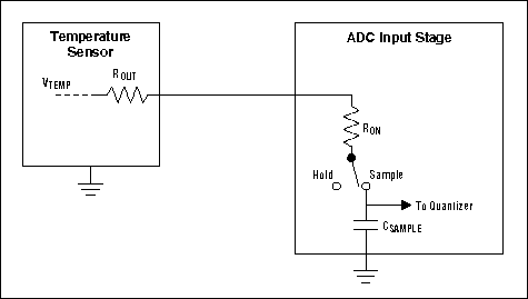
Figure 1. This is a conceptual schematic of an analog temperature sensor driving the input of a sampling ADC. A temperature sensor with excessive output resistance causes errors by preventing the sampling capacitor from charging fully during the sampling period.
For accurate sampling of the input signal, the capacitor must fully charge during the time that the switch is closed. For a 10-bit ADC, this means that the time constant of the total source resistance (including the switch on-resistance) multiplied by the sampling capacitance (say, 10pF) must be less than about 10% of the time that the switch is closed:
(RON + ROUT) x CSAMPLE < 0.1 x TSAMPLEwhere RON is the sampling switch on-resistance, ROUT is the output resistance of the temperature sensor, CSAMPLE is the sample-hold capacitance, and TSAMPLE is time that the sampling switch is closed.
This places a constraint on the value of the source resistance driving the ADC input. Most general-purpose ADCs have maximum source-impedance limits somewhere between 1kΩ and 10kΩ.
Analog temperature sensors have output resistances that range from less than 100Ω to several kΩ; some of the higher-impedance output stages are incompatible with certain ADC inputs. The MAX6605 has a 240Ω output impedance and is compatible with virtually all general-purpose ADCs.
If a temperature sensor has excessive output resistance, connecting a capacitor between the ADC input pin and ground can reduce the effective source impedance and minimize errors. The capacitor should usually be on the order of a thousand times' the value of the sampling capacitor, so a 10nF capacitor is generally sufficient. The time between samples should be long enough to allow the capacitor voltage to approximate the sensor's output voltage to within the required accuracy. Ten time constants should be sufficient for a 10-bit ADC; therefore, for a 1k source resistance and a 10nF capacitor, a period of at least 100μs between conversions should be adequate.
Load Capacitance
Even when a capacitor isn't needed to compensate for excessive source resistance, it is common practice to place a capacitor across the ADC input pin, as shown in Figure 2. This helps to filter noise that has been picked up on the traces leading to the sensor. Common values are on the order of 1nF to 100nF. As discussed above, the sampling rate has to be slow enough to allow the capacitor to charge sufficiently between conversions.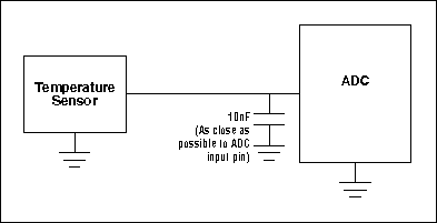
Figure 2. A capacitor is often connected across the ADC input to filter noise or help reduce errors due to excessive sensor output resistance. Note that the sampling rate must allow several time constants between conversions.
Ideally, the temperature sensor is able to drive this capacitance without oscillating. (The MAX6605 is stable with load capacitance from 1nF to infinity.) Many other analog temperature sensors become unstable when loaded with a few hundred picofarads of load capacitance; these can sometimes be isolated from the capacitance by the addition of a series resistor with a value of a few hundred ohms. Note that adding a resistor between the sensor output and the ADC input can necessitate slowing the sampling rate further.
Reference Voltage, Temperature Range, and Resolution
The reference voltage used with the ADC affects the useful temperature range and the temperature measurement resolution. As an example, consider the MAX6605 temperature sensor driving a 10-bit ADC with a 2.5V reference. This ADC might be embedded within a microcontroller, or, in applications requiring higher performance, it might be a separate ADC such as the MAX1248.With a 2.5V reference, each LSB will have a weight of
2.5V/1024LSBs = 2.44mV/LSBThe nominal slope of the MAX6605 temperature sensor's output is 11.9mV/°C, so each LSB will correspond to
(2.44mV/LSB)/(11.9mV/°C) = 0.205°C/LSBThe MAX6605 produces a nominal output voltage of 2.26V at 125°C; thus, its temperature and voltage ranges are compatible with the 2.5V reference.
 電子發(fā)燒友App










評論