

概述
在說CdS光電管之間有一些區別:
IR檢測器經過特殊過濾以用于紅外光,它們不擅長檢測可見光。另一方面,光電管擅長檢測黃/綠可見光,而不擅長紅外光
紅外檢測器內部有一個解調器,用于尋找38 KHz的調制IR。只是無法檢測到紅外LED發光,它必須以38KHz的PWM頻率閃爍。光電管沒有任何類型的解調器,可以檢測到光電管響應速度(大約1KHz)內的任何頻率(包括DC)。
紅外檢測器是數字輸出的-它們可以檢測38KHz紅外信號,輸出低電平(0V)或它們沒有檢測到并輸出高電平(5V)。光電管就像電阻一樣,電阻會根據它們所暴露的光量而變化
在本教程中,我們將展示如何
測試紅外傳感器以確保其正常工作
將原始IR代碼讀入微控制器
創建相機間隔計
從微控制器上的遙控器收聽“命令”
某些統計信息
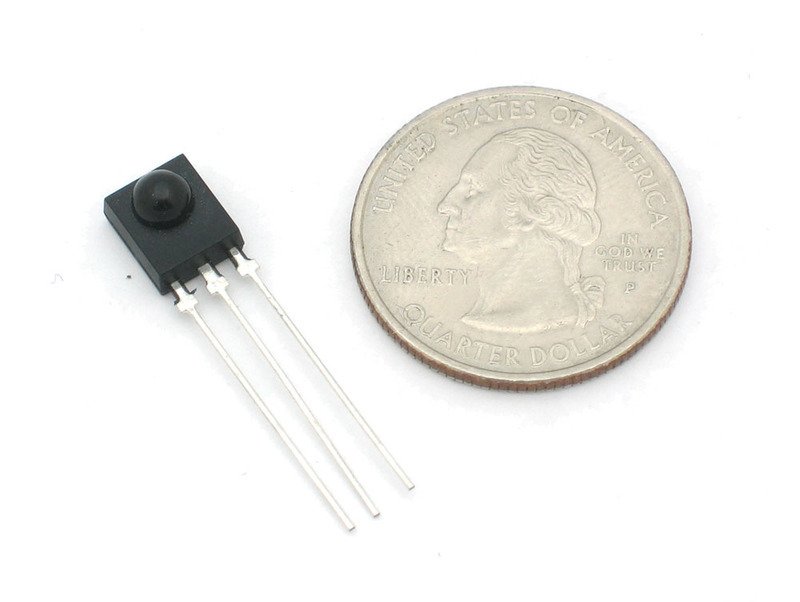
這些統計信息適用于Adafruit商店(也稱為PNA4602)中的紅外探測器。幾乎所有光電管的規格都略有不同,盡管它們的工作原理幾乎相同。如果有數據表,您將需要參考它
尺寸:正方形,探測器面積7mm x 8mm
輸出:檢測到38KHz載波時為0V(低),否則為5V(高)
靈敏度范圍::800nm至1100nm,峰值響應在940nm。頻率范圍為35KHz至41KHz,峰值檢測頻率為38KHz
電源: 3-5V DC 3mA
PNA4602數據表( (現已停產)或 GP1UX311QS 或 TSOP38238 (與引腳兼容的替代品)
您可以測量的內容
從這些數據表圖表中可以看到,峰值頻率檢測在 38 KHz ,峰值LED顏色為 940 nm 。您可以使用大約35 KHz至41 KHz的頻率,但靈敏度會下降,因此遠距離也無法檢測到。同樣,您可以使用850至1100 nm的LED,但它們不能與900至1000nm的LED一樣工作,因此請確保獲得匹配的LED!
嘗試獲取940nm-記住940nm不是可見光(它的紅外光)!
測試IR傳感器
由于傳感器內部有半導體/芯片,因此必須使用3-5V的電源才能正常工作。將其與光電池和FSR進行對比,它們像電阻一樣發揮作用,因此可以用萬用表簡單地進行測試。

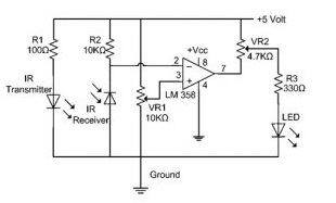
在這里,我們將按以下方式連接檢測器:
Pin 1是輸出,因此我們將其接線連接到可見的LED和電阻器
引腳2接地
引腳3為VCC,連接到3-5V
當檢測器看到IR時信號,它將拉低輸出,從而打開LED指示燈-由于LED指示燈為紅色,因此我們比IR更容易看到它!
我們將使用4節3號1.3V電池(我使用NiMH),以便為傳感器供電大約4V。
2個電池(3V)可能太少。如果您有三節AA電池座,則3塊電池應該沒問題
如果周圍有一個電池,也可以從Arduino等微控制器獲得5V電壓。接地連接到中間引腳。
紅色LED的正(較長)頭連接到+ 6V引腳,負(較短引線)通過200到1000歐姆的電阻連接到第一個引腳。
現在抓住電視,DVD,計算機等遙控器,將其指向檢測器,同時按下一些按鈕,每當遙控器發出信號時,LED應該會閃爍兩次按下。
紅外遙控信號
現在我們知道傳感器可以正常工作了,我們想弄清楚發送的是什么嗎?但是在執行此操作之前,我們首先要仔細檢查數據是如何從紅外遙控器(在您的手中)發送到紅外接收傳感器(在面包板上)的
在此示例中,我們將使用索尼電源/off來自Sony電視遙控器的IR代碼。它非常簡單,并且經常記錄在案!
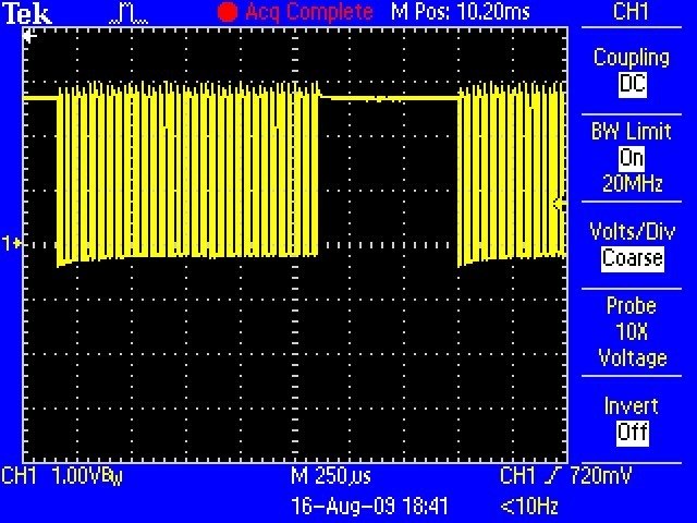
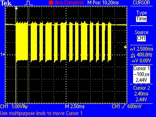
假設我們有一個Sony遙控器,我們可以確切地查看從IR LED發射出的光。我們將連接一個基本的光傳感器(如基本的光電管!)并進行監聽。我們不會使用像PNA4602這樣的解碼器(到目前為止),因為我們希望看到未解碼的信號。我們看到的是以下內容:

基本上我們看到脈沖或IR信號。黃色的“塊”表示IR LED處于傳輸狀態,而只有一條線時,IR LED處于熄滅狀態。 (請注意,處于3VDC的電壓僅僅是由于我連接傳感器的方式,如果我將上拉交換為下拉,則它將在地面。)
第一個“塊”大約是2.5毫秒長(請參見側面的光標和測量值)
如果您放大這些塊之一……
您會發現它們并不是真正的“障礙”,而是非常快的脈沖! p》
如果一直放大…
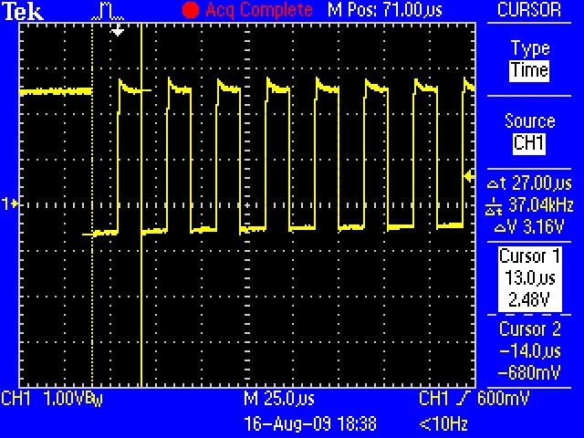
您可以測量IR脈沖的頻率。正如您可以從光標和側面的測量值看出的那樣,頻率大約為37.04KHz
OK,因此現在我們可以了解如何發送IR代碼了。紅外發射器LED迅速以38KHz的高頻率脈沖化(PWM-脈寬調制),然后該PWM同樣被慢速地脈沖化開和關,時間約為1-3 ms。
為什么不只打開和關閉LED?為什么會有PWM“載波”脈沖?原因很多!
一個原因是,這會使LED冷卻。紅外LED最多可消耗1 A(1000毫安!)的電流。大多數LED僅占用20mA左右。這意味著IR LED是為大功率噴砂而設計的,但它們只能承受幾微秒的時間。通過PWM‘ing,可以讓LED冷卻一半的時間
另一個原因是電視將僅收聽特定頻率的PWM。因此,在37KHz的Sony遙控器上無法使用僅要求50KHz的JVC DVD播放器。
最后,最重要的原因是通過對載波施加脈沖,可以減少環境照明的影響。電視只尋找時鐘頻率約為37KHz的亮度變化。就像對我們來說分辨音頻音調之間的差異比確定音調的精確音高(至少對大多數人而言)一樣容易
好,所以現在我們知道了載波頻率。其37KHz。接下來讓我們找到脈沖寬度!
回頭看第一張示波器圖片
第一個脈沖為2.5毫秒。我們可以使用光標來測量剩余的脈沖。我將為您保留12張圖像,讓您知道脈沖是:
PWM ON 關閉
2.4毫秒0.6毫秒
1.2 ms0.6 ms
0.6 ms0.6 ms
1.2 ms0.6 ms
0.6 ms0.6 ms
1.2 ms0.6 ms
0.6 ms0.6 ms
0.6毫秒0.6毫秒
1.2毫秒0.6毫秒
0.6毫秒0.6毫秒
0.6毫秒0.6毫秒
0.6毫秒0.6毫秒
0.6毫秒270毫秒
因此,假設您沒有價格為$ 1000的示波器,您還能如何讀取這些信號?像PNA4602這樣的IR解碼器很好地幫了我們一個忙,它“濾出”了38KHz信號,因此我們只能得到毫粘范圍內的大信號塊。對于微控制器來說,這要容易得多。那就是我們在下一節中要做的!
使用紅外傳感器
好消息是,連接此傳感器非常容易。只需將輸出連接到數字引腳即可。壞消息是,Arduino的友好的 digitalRead()程序太慢了,無法可靠地讀取快速信號,因此我們直接從引腳D2使用硬件引腳讀取功能,這就是行“ IRpin_PIN&BV(IRpin))”。此技巧特定于基于ATmega328的板,例如Arduino Uno,Adafruit Metro等。

完全組裝的Adafruit METRO 328-兼容Arduino IDE
產品ID:50
我們肯定喜歡Adafruit的ATmega328,并且將lota用于我們自己的項目。該處理器具有大量的GPIO,模擬輸入,硬件UART SPI和I2C,。。.
$ 17.50
入庫
添加到購物車
下載:Project Zip 或 ir_codes。 ino | 在Github上查看
復制代碼
/* Raw IR decoder sketch!
This sketch/program uses the Arduno and a PNA4602 to
decode IR received. This can be used to make a IR receiver
(by looking for a particular code)
or transmitter (by pulsing an IR LED at ~38KHz for the
durations detected
Code is public domain, check out www.ladyada.net and adafruit.com
for more tutorials!
*/
// We need to use the ’raw‘ pin reading methods
// because timing is very important here and the digitalRead()
// procedure is slower!
//uint8_t IRpin = 2;
// Digital pin #2 is the same as Pin D2 see
// http://arduino.cc/en/Hacking/PinMapping168 for the ’raw‘ pin mapping
#define IRpin_PIN PIND
#define IRpin 2
// the maximum pulse we’ll listen for - 65 milliseconds is a long time
#define MAXPULSE 65000
// what our timing resolution should be, larger is better
// as its more ‘precise’ - but too large and you wont get
// accurate timing
#define RESOLUTION 20
// we will store up to 100 pulse pairs (this is -a lot-)
uint16_t pulses[100][2]; // pair is high and low pulse
uint8_t currentpulse = 0; // index for pulses we‘re storing
void setup(void) {
Serial.begin(9600);
Serial.println(“Ready to decode IR!”);
}
void loop(void) {
uint16_t highpulse, lowpulse; // temporary storage timing
highpulse = lowpulse = 0; // start out with no pulse length
// while (digitalRead(IRpin)) { // this is too slow!
while (IRpin_PIN & (1 《《 IRpin)) {
// pin is still HIGH
// count off another few microseconds
highpulse++;
delayMicroseconds(RESOLUTION);
// If the pulse is too long, we ’timed out‘ - either nothing
// was received or the code is finished, so print what
// we’ve grabbed so far, and then reset
if ((highpulse 》= MAXPULSE) && (currentpulse != 0)) {
printpulses();
currentpulse=0;
return;
}
}
// we didn‘t time out so lets stash the reading
pulses[currentpulse][0] = highpulse;
// same as above
while (! (IRpin_PIN & _BV(IRpin))) {
// pin is still LOW
lowpulse++;
delayMicroseconds(RESOLUTION);
if ((lowpulse 》= MAXPULSE) && (currentpulse != 0)) {
printpulses();
currentpulse=0;
return;
}
}
pulses[currentpulse][1] = lowpulse;
// we read one high-low pulse successfully, continue!
currentpulse++;
}
void printpulses(void) {
Serial.println(“ Received: OFF ON”);
for (uint8_t i = 0; i 《 currentpulse; i++) {
Serial.print(pulses[i][0] * RESOLUTION, DEC);
Serial.print(“ usec, ”);
Serial.print(pulses[i][1] * RESOLUTION, DEC);
Serial.println(“ usec”);
}
// print it in a ’array‘ format
Serial.println(“int IRsignal[] = {”);
Serial.println(“// ON, OFF ”);
for (uint8_t i = 0; i 《 currentpulse-1; i++) {
//Serial.print(“ ”); // tab
Serial.print(“pulseIR(”);
Serial.print(pulses[i][1] * RESOLUTION , DEC);
Serial.print(“);”);
Serial.println(“”);
//Serial.print(“ ”);
Serial.print(“delayMicroseconds(”);
Serial.print(pulses[i+1][0] * RESOLUTION , DEC);
Serial.println(“);”);
}
//Serial.print(“ ”); // tab
Serial.print(“pulseIR(”);
Serial.print(pulses[currentpulse-1][1] * RESOLUTION, DEC);
Serial.print(“);”);
}
如果您在指向Sony IR遙控器并按下ON按鈕的同時運行此程序,則會得到以下內容。。.
如果您忽略第一個OFF脈沖(這只是從Arduino開始的時間打開第一個接收到的IR信號)和最后一個打開脈沖(即下一個代碼的開始),您會找到Sony電源代碼:
PWM開啟關閉
2.5 ms0.6毫秒
1.2 ms0.6 ms
0.6 ms0.6 ms
1.2 ms0.6 ms
0.6 ms0.6 ms
1.2 ms0.6 ms
0.6 ms0.6 ms
0.6 ms0.6 ms
1.2 ms0.6 ms
0.6 ms0.6 ms
0.6 ms0.6 ms
0.6毫秒0.6毫秒
0.6毫秒27.2毫秒
現在,我們可以讀取紅外代碼了,制作一個間隔計
好,讓我們做一個基礎項目。我們要做的第一個是制作一個間隔計。間隔計基本上是一種電子設備,可使照相機每隔幾分鐘左右關閉一次。這可以用于游戲中時光倒流項目或風箏攝影或其他照片項目。
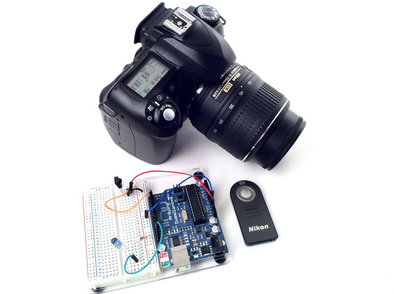
我們將要使用的相機具有一個紅外遙控器,您可以將其關閉(大多數高端相機都有)。

首先我們要弄清楚通過讀取按下按鈕時發送的信號來讀出代碼。然后,我們將獲取這些數據,并使Arduino每分鐘一次將該代碼輸出到IR LED中。
好,第一步很簡單,將遙控器對準IR傳感器,然后按一下按鈕,我們得到了
看起來像發送的數據是:
PWM ON OFF
2.0 ms27 ms
0.4 ms1.5 ms
0.5 ms3.5 ms
0.5 ms62.2毫秒
2.0毫秒27毫秒
0.5毫秒1.5毫秒
0.5毫秒3.5毫秒
0.5 ms
如果仔細觀察,您會發現它實際上只是
PWM ON OFF
2.0 ms27 ms
0.4毫秒1.5毫秒
0.5毫秒3.5毫秒
0.5毫秒62.2毫秒
已發送兩次。兩次發送相同的信號是很常見的-加倍以確保收到信號
下一步,我們需要將940nm IR LED連接到Arduino的輸出

然后我們將寫一個草圖
下載: Project Zip 或 intervalometer.ino | 在Github上查看
復制代碼
// This sketch will send out a Nikon D50 trigger signal (probably works with most Nikons)
// See the full tutorial at https://learn.adafruit.com/ir-sensor/making-an-intervalometer
// MIT License, attribution appreciated Limor Fried, Adafruit Industries
int IRledPin = 13; // LED connected to digital pin 13
// The setup() method runs once, when the sketch starts
void setup() {
// initialize the IR digital pin as an output:
pinMode(IRledPin, OUTPUT);
Serial.begin(9600);
}
void loop()
{
Serial.println(“Sending IR signal”);
SendNikonCode();
delay(60*1000); // wait one minute (60 seconds * 1000 milliseconds)
}
// This procedure sends a 38KHz pulse to the IRledPin
// for a certain # of microseconds. We’ll use this whenever we need to send codes
void pulseIR(long microsecs) {
// we‘ll count down from the number of microseconds we are told to wait
cli(); // this turns off any background interrupts
while (microsecs 》 0) {
// 38 kHz is about 13 microseconds high and 13 microseconds low
digitalWrite(IRledPin, HIGH); // this takes about 3 microseconds to happen
delayMicroseconds(10); // hang out for 10 microseconds, you can also change this to 9 if its not working
digitalWrite(IRledPin, LOW); // this also takes about 3 microseconds
delayMicroseconds(10); // hang out for 10 microseconds, you can also change this to 9 if its not working
// so 26 microseconds altogether
microsecs -= 26;
}
sei(); // this turns them back on
}
void SendNikonCode() {
// This is the code for my particular Nikon, for others use the tutorial
// to ’grab‘ the proper code from the remote
pulseIR(2080);
delay(27);
pulseIR(440);
delayMicroseconds(1500);
pulseIR(460);
delayMicroseconds(3440);
pulseIR(480);
delay(65); // wait 65 milliseconds before sending it again
pulseIR(2000);
delay(27);
pulseIR(440);
delayMicroseconds(1500);
pulseIR(460);
delayMicroseconds(3440);
pulseIR(480);
}
void pulseIR(long microsecs)是我們的幫助程序,它將像之前看到的那樣創建PWM IR信號。我使用示波器進行了微調,以使延遲加起來正確。我們使用不常討論的cli()和sei()過程關閉中斷。 Arduino在后臺執行了一些操作,例如尋找要讀取或寫入的串行數據,跟蹤時間等。大多數情況下,我們可以忽略它,但是對于像這樣的微妙的高速信號,我們希望保持安靜,以便我們會得到一個很好的干凈信號
如果您查看SendNikonCode(),您將看到我們在上一個項目中通過對來自紅外傳感器的脈沖進行計時推導出的IR命令代碼。

并且效果很好,請確保將IR LED正確對準相機。
讀取IR命令
對于我們的最終項目,我們將使用遙控器將消息發送到微控制器。例如,這對于可以用IR遙控器控制的機器人可能很有用。這對于想要在遠處無需電線控制的項目也可能是好的。您可以使用任何所需的遙控器,也可以從毫無戒心的行家那里竊取其中之一。

我們將使用之前草圖中的代碼進行原始紅外讀取,但是這次我們將編輯打印機的外部它為我們提供了C數組中的脈沖,這將使我們更易于用于模式匹配。
下載:文件
復制代碼
void printpulses(void) {
Serial.println(“ Received: OFF ON”);
for (uint8_t i = 0; i 《 currentpulse; i++) {
Serial.print(pulses[i][0] * RESOLUTION, DEC);
Serial.print(“ usec, ”);
Serial.print(pulses[i][1] * RESOLUTION, DEC);
Serial.println(“ usec”);
}
// print it in a ’array‘ format
Serial.println(“int IRsignal[] = {”);
Serial.println(“// ON, OFF (in 10’s of microseconds)”);
for (uint8_t i = 0; i 《 currentpulse-1; i++) {
Serial.print(“ ”); // tab
Serial.print(pulses[i][1] * RESOLUTION / 10, DEC);
Serial.print(“, ”);
Serial.print(pulses[i+1][0] * RESOLUTION / 10, DEC);
Serial.println(“,”);
}
Serial.print(“ ”); // tab
Serial.print(pulses[currentpulse-1][1] * RESOLUTION / 10, DEC);
Serial.print(“, 0};”);
} void printpulses(void) {
Serial.println(“ Received: OFF ON”);
for (uint8_t i = 0; i 《 currentpulse; i++) {
Serial.print(pulses[i][0] * RESOLUTION, DEC);
Serial.print(“ usec, ”);
Serial.print(pulses[i][1] * RESOLUTION, DEC);
Serial.println(“ usec”);
}
// print it in a ‘array’ format
Serial.println(“int IRsignal[] = {”);
Serial.println(“// ON, OFF (in 10‘s of microseconds)”);
for (uint8_t i = 0; i 《 currentpulse-1; i++) {
Serial.print(“ ”); // tab
Serial.print(pulses[i][1] * RESOLUTION / 10, DEC);
Serial.print(“, ”);
Serial.print(pulses[i+1][0] * RESOLUTION / 10, DEC);
Serial.println(“,”);
}
Serial.print(“ ”); // tab
Serial.print(pulses[currentpulse-1][1] * RESOLUTION / 10, DEC);
Serial.print(“, 0};”);
}
我上傳了新草圖,并按了 Play Apple遙控器上的按鈕并獲得以下內容:
下載:文件
復制代碼
int IRsignal[] = { // ON, OFF (in 10’s of microseconds)
912, 438,
68, 48,
68, 158,
68, 158,
68, 158,
68, 48,
68, 158,
68, 158,
68, 158,
70, 156,
70, 158,
68, 158,
68, 48,
68, 46,
70, 46,
68, 46,
68, 160,
68, 158,
70, 46,
68, 158,
68, 46,
70, 46,
68, 48,
68, 46,
68, 48,
66, 48,
68, 48,
66, 160,
66, 50,
66, 160,
66, 52,
64, 160,
66, 48,
66, 3950,
908, 214,
66, 3012,
908, 212,
68, 0}; int IRsignal[] = { // ON, OFF (in 10‘s of microseconds)
912, 438,
68, 48,
68, 158,
68, 158,
68, 158,
68, 48,
68, 158,
68, 158,
68, 158,
70, 156,
70, 158,
68, 158,
68, 48,
68, 46,
70, 46,
68, 46,
68, 160,
68, 158,
70, 46,
68, 158,
68, 46,
70, 46,
68, 48,
68, 46,
68, 48,
66, 48,
68, 48,
66, 160,
66, 50,
66, 160,
66, 52,
64, 160,
66, 48,
66, 3950,
908, 214,
66, 3012,
908, 212,
68, 0};
我們將嘗試檢測該代碼。
讓我們開始一個名為 IR Commander的新草圖(您可以從GitHub下方的綠色按鈕下載最終代碼,或在完整的代碼列表中單擊Download Project Zip)。
打開此頁面上代碼的GitHub存儲庫
下載:Project Zip 或 ircommander.ino | 在Github上查看
復制代碼
/* Raw IR commander
This sketch/program uses the Arduno and a PNA4602 to
decode IR received. It then attempts to match it to a previously
recorded IR signal. Limor Fried, Adafruit Industries
MIT License, please attribute
check out learn.adafruit.com for more tutorials!
*/
// We need to use the ’raw‘ pin reading methods
// because timing is very important here and the digitalRead()
// procedure is slower!
//uint8_t IRpin = 2;
// Digital pin #2 is the same as Pin D2 see
// http://arduino.cc/en/Hacking/PinMapping168 for the ’raw‘ pin mapping
#define IRpin_PIN PIND
#define IRpin 2
// the maximum pulse we’ll listen for - 65 milliseconds is a long time
#define MAXPULSE 65000
#define NUMPULSES 50
// what our timing resolution should be, larger is better
// as its more ‘precise’ - but too large and you wont get
// accurate timing
#define RESOLUTION 20
// What percent we will allow in variation to match the same code
#define FUZZINESS 20
// we will store up to 100 pulse pairs (this is -a lot-)
uint16_t pulses[NUMPULSES][2]; // pair is high and low pulse
uint8_t currentpulse = 0; // index for pulses we‘re storing
#include “ircommander.h”
void setup(void) {
Serial.begin(9600);
Serial.println(“Ready to decode IR!”);
}
void loop(void) {
int numberpulses;
numberpulses = listenForIR();
Serial.print(“Heard ”);
Serial.print(numberpulses);
Serial.println(“-pulse long IR signal”);
if (IRcompare(numberpulses, ApplePlaySignal,sizeof(ApplePlaySignal)/4)) {
Serial.println(“PLAY”);
}
if (IRcompare(numberpulses, AppleRewindSignal,sizeof(AppleRewindSignal)/4)) {
Serial.println(“REWIND”);
}
if (IRcompare(numberpulses, AppleForwardSignal,sizeof(AppleForwardSignal)/4)) {
Serial.println(“FORWARD”);
}
delay(500);
}
//KGO: added size of compare sample. Only compare the minimum of the two
boolean IRcompare(int numpulses, int Signal[], int refsize) {
int count = min(numpulses,refsize);
Serial.print(“count set to: ”);
Serial.println(count);
for (int i=0; i《 count-1; i++) {
int oncode = pulses[i][1] * RESOLUTION / 10;
int offcode = pulses[i+1][0] * RESOLUTION / 10;
#ifdef DEBUG
Serial.print(oncode); // the ON signal we heard
Serial.print(“ - ”);
Serial.print(Signal[i*2 + 0]); // the ON signal we want
#endif
// check to make sure the error is less than FUZZINESS percent
if ( abs(oncode - Signal[i*2 + 0]) 《= (Signal[i*2 + 0] * FUZZINESS / 100)) {
#ifdef DEBUG
Serial.print(“ (ok)”);
#endif
} else {
#ifdef DEBUG
Serial.print(“ (x)”);
#endif
// we didn’t match perfectly, return a false match
return false;
}
#ifdef DEBUG
Serial.print(“ ”); // tab
Serial.print(offcode); // the OFF signal we heard
Serial.print(“ - ”);
Serial.print(Signal[i*2 + 1]); // the OFF signal we want
#endif
if ( abs(offcode - Signal[i*2 + 1]) 《= (Signal[i*2 + 1] * FUZZINESS / 100)) {
#ifdef DEBUG
Serial.print(“ (ok)”);
#endif
} else {
#ifdef DEBUG
Serial.print(“ (x)”);
#endif
// we didn‘t match perfectly, return a false match
return false;
}
#ifdef DEBUG
Serial.println();
#endif
}
// Everything matched!
return true;
}
int listenForIR(void) {
currentpulse = 0;
while (1) {
uint16_t highpulse, lowpulse; // temporary storage timing
highpulse = lowpulse = 0; // start out with no pulse length
// while (digitalRead(IRpin)) { // this is too slow!
while (IRpin_PIN & (1 《《 IRpin)) {
// pin is still HIGH
// count off another few microseconds
highpulse++;
delayMicroseconds(RESOLUTION);
// If the pulse is too long, we ’timed out‘ - either nothing
// was received or the code is finished, so print what
// we’ve grabbed so far, and then reset
// KGO: Added check for end of receive buffer
if (((highpulse 》= MAXPULSE) && (currentpulse != 0))|| currentpulse == NUMPULSES) {
return currentpulse;
}
}
// we didn‘t time out so lets stash the reading
pulses[currentpulse][0] = highpulse;
// same as above
while (! (IRpin_PIN & _BV(IRpin))) {
// pin is still LOW
lowpulse++;
delayMicroseconds(RESOLUTION);
// KGO: Added check for end of receive buffer
if (((lowpulse 》= MAXPULSE) && (currentpulse != 0))|| currentpulse == NUMPULSES) {
return currentpulse;
}
}
pulses[currentpulse][1] = lowpulse;
// we read one high-low pulse successfully, continue!
currentpulse++;
}
}
void printpulses(void) {
Serial.println(“ Received: OFF ON”);
for (uint8_t i = 0; i 《 currentpulse; i++) {
Serial.print(pulses[i][0] * RESOLUTION, DEC);
Serial.print(“ usec, ”);
Serial.print(pulses[i][1] * RESOLUTION, DEC);
Serial.println(“ usec”);
}
// print it in a ’array‘ format
Serial.println(“int IRsignal[] = {”);
Serial.println(“// ON, OFF (in 10’s of microseconds)”);
for (uint8_t i = 0; i 《 currentpulse-1; i++) {
Serial.print(“ ”); // tab
Serial.print(pulses[i][1] * RESOLUTION / 10, DEC);
Serial.print(“, ”);
Serial.print(pulses[i+1][0] * RESOLUTION / 10, DEC);
Serial.println(“,”);
}
Serial.print(“ ”); // tab
Serial.print(pulses[currentpulse-1][1] * RESOLUTION / 10, DEC);
Serial.print(“, 0};”);
}
/* Raw IR commander
This sketch/program uses the Arduno and a PNA4602 to
decode IR received. It then attempts to match it to a previously
recorded IR signal. Limor Fried, Adafruit Industries
MIT License, please attribute
check out learn.adafruit.com for more tutorials!
*/
// We need to use the ‘raw’ pin reading methods
// because timing is very important here and the digitalRead()
// procedure is slower!
//uint8_t IRpin = 2;
// Digital pin #2 is the same as Pin D2 see
// http://arduino.cc/en/Hacking/PinMapping168 for the ‘raw’ pin mapping
#define IRpin_PIN PIND
#define IRpin 2
// the maximum pulse we‘ll listen for - 65 milliseconds is a long time
#define MAXPULSE 65000
#define NUMPULSES 50
// what our timing resolution should be, larger is better
// as its more ’precise‘ - but too large and you wont get
// accurate timing
#define RESOLUTION 20
// What percent we will allow in variation to match the same code
#define FUZZINESS 20
// we will store up to 100 pulse pairs (this is -a lot-)
uint16_t pulses[NUMPULSES][2]; // pair is high and low pulse
uint8_t currentpulse = 0; // index for pulses we’re storing
#include “ircommander.h”
void setup(void) {
Serial.begin(9600);
Serial.println(“Ready to decode IR!”);
}
void loop(void) {
int numberpulses;
numberpulses = listenForIR();
Serial.print(“Heard ”);
Serial.print(numberpulses);
Serial.println(“-pulse long IR signal”);
if (IRcompare(numberpulses, ApplePlaySignal,sizeof(ApplePlaySignal)/4)) {
Serial.println(“PLAY”);
}
if (IRcompare(numberpulses, AppleRewindSignal,sizeof(AppleRewindSignal)/4)) {
Serial.println(“REWIND”);
}
if (IRcompare(numberpulses, AppleForwardSignal,sizeof(AppleForwardSignal)/4)) {
Serial.println(“FORWARD”);
}
delay(500);
}
//KGO: added size of compare sample. Only compare the minimum of the two
boolean IRcompare(int numpulses, int Signal[], int refsize) {
int count = min(numpulses,refsize);
Serial.print(“count set to: ”);
Serial.println(count);
for (int i=0; i《 count-1; i++) {
int oncode = pulses[i][1] * RESOLUTION / 10;
int offcode = pulses[i+1][0] * RESOLUTION / 10;
#ifdef DEBUG
Serial.print(oncode); // the ON signal we heard
Serial.print(“ - ”);
Serial.print(Signal[i*2 + 0]); // the ON signal we want
#endif
// check to make sure the error is less than FUZZINESS percent
if ( abs(oncode - Signal[i*2 + 0]) 《= (Signal[i*2 + 0] * FUZZINESS / 100)) {
#ifdef DEBUG
Serial.print(“ (ok)”);
#endif
} else {
#ifdef DEBUG
Serial.print(“ (x)”);
#endif
// we didn‘t match perfectly, return a false match
return false;
}
#ifdef DEBUG
Serial.print(“ ”); // tab
Serial.print(offcode); // the OFF signal we heard
Serial.print(“ - ”);
Serial.print(Signal[i*2 + 1]); // the OFF signal we want
#endif
if ( abs(offcode - Signal[i*2 + 1]) 《= (Signal[i*2 + 1] * FUZZINESS / 100)) {
#ifdef DEBUG
Serial.print(“ (ok)”);
#endif
} else {
#ifdef DEBUG
Serial.print(“ (x)”);
#endif
// we didn’t match perfectly, return a false match
return false;
}
#ifdef DEBUG
Serial.println();
#endif
}
// Everything matched!
return true;
}
int listenForIR(void) {
currentpulse = 0;
while (1) {
uint16_t highpulse, lowpulse; // temporary storage timing
highpulse = lowpulse = 0; // start out with no pulse length
// while (digitalRead(IRpin)) { // this is too slow!
while (IRpin_PIN & (1 《《 IRpin)) {
// pin is still HIGH
// count off another few microseconds
highpulse++;
delayMicroseconds(RESOLUTION);
// If the pulse is too long, we ‘timed out’ - either nothing
// was received or the code is finished, so print what
// we‘ve grabbed so far, and then reset
// KGO: Added check for end of receive buffer
if (((highpulse 》= MAXPULSE) && (currentpulse != 0))|| currentpulse == NUMPULSES) {
return currentpulse;
}
}
// we didn’t time out so lets stash the reading
pulses[currentpulse][0] = highpulse;
// same as above
while (! (IRpin_PIN & _BV(IRpin))) {
// pin is still LOW
lowpulse++;
delayMicroseconds(RESOLUTION);
// KGO: Added check for end of receive buffer
if (((lowpulse 》= MAXPULSE) && (currentpulse != 0))|| currentpulse == NUMPULSES) {
return currentpulse;
}
}
pulses[currentpulse][1] = lowpulse;
// we read one high-low pulse successfully, continue!
currentpulse++;
}
}
void printpulses(void) {
Serial.println(“ Received: OFF ON”);
for (uint8_t i = 0; i 《 currentpulse; i++) {
Serial.print(pulses[i][0] * RESOLUTION, DEC);
Serial.print(“ usec, ”);
Serial.print(pulses[i][1] * RESOLUTION, DEC);
Serial.println(“ usec”);
}
// print it in a ‘array’ format
Serial.println(“int IRsignal[] = {”);
Serial.println(“// ON, OFF (in 10‘s of microseconds)”);
for (uint8_t i = 0; i 《 currentpulse-1; i++) {
Serial.print(“ ”); // tab
Serial.print(pulses[i][1] * RESOLUTION / 10, DEC);
Serial.print(“, ”);
Serial.print(pulses[i+1][0] * RESOLUTION / 10, DEC);
Serial.println(“,”);
}
Serial.print(“ ”); // tab
Serial.print(pulses[currentpulse-1][1] * RESOLUTION / 10, DEC);
Serial.print(“, 0};”);
}
下載:Project Zip 或 ircommander .h | 在Github上查看
復制代碼
/******************* our codes ************/
int ApplePlaySignal[] = {
// ON, OFF (in 10’s of microseconds)
912, 438,
68, 48,
68, 158,
68, 158,
68, 158,
68, 48,
68, 158,
68, 158,
68, 158,
70, 156,
70, 158,
68, 158,
68, 48,
68, 46,
70, 46,
68, 46,
68, 160,
68, 158,
70, 46,
68, 158,
68, 46,
70, 46,
68, 48,
68, 46,
68, 48,
66, 48,
68, 48,
66, 160,
66, 50,
66, 160,
66, 50,
64, 160,
66, 50,
66, 3950,
908, 214,
66, 3012,
908, 212,
68, 0};
int AppleForwardSignal[] = {
// ON, OFF (in 10‘s of microseconds)
908, 444,
64, 50,
66, 162,
64, 162,
64, 162,
64, 52,
64, 162,
64, 162,
64, 162,
64, 164,
62, 164,
64, 162,
64, 52,
62, 52,
64, 52,
64, 50,
64, 164,
64, 50,
64, 164,
64, 162,
64, 50,
66, 50,
66, 50,
64, 50,
66, 50,
64, 52,
64, 50,
66, 160,
66, 50,
64, 162,
66, 50,
64, 162,
64, 50,
66, 3938,
906, 214,
66, 3014,
906, 214,
64, 0};
int AppleRewindSignal[] = {
// ON, OFF (in 10’s of microseconds)
908, 442,
66, 48,
66, 162,
66, 160,
66, 160,
66, 50,
66, 160,
66, 160,
66, 160,
68, 158,
68, 160,
66, 160,
66, 50,
66, 48,
66, 50,
66, 48,
66, 162,
66, 160,
66, 48,
68, 48,
66, 160,
66, 50,
66, 50,
66, 48,
66, 50,
66, 48,
68, 48,
66, 160,
66, 50,
66, 160,
66, 50,
66, 160,
66, 48,
68, 3936,
906, 214,
66, 0};
/******************* our codes ************/
int ApplePlaySignal[] = {
// ON, OFF (in 10‘s of microseconds)
912, 438,
68, 48,
68, 158,
68, 158,
68, 158,
68, 48,
68, 158,
68, 158,
68, 158,
70, 156,
70, 158,
68, 158,
68, 48,
68, 46,
70, 46,
68, 46,
68, 160,
68, 158,
70, 46,
68, 158,
68, 46,
70, 46,
68, 48,
68, 46,
68, 48,
66, 48,
68, 48,
66, 160,
66, 50,
66, 160,
66, 50,
64, 160,
66, 50,
66, 3950,
908, 214,
66, 3012,
908, 212,
68, 0};
int AppleForwardSignal[] = {
// ON, OFF (in 10’s of microseconds)
908, 444,
64, 50,
66, 162,
64, 162,
64, 162,
64, 52,
64, 162,
64, 162,
64, 162,
64, 164,
62, 164,
64, 162,
64, 52,
62, 52,
64, 52,
64, 50,
64, 164,
64, 50,
64, 164,
64, 162,
64, 50,
66, 50,
66, 50,
64, 50,
66, 50,
64, 52,
64, 50,
66, 160,
66, 50,
64, 162,
66, 50,
64, 162,
64, 50,
66, 3938,
906, 214,
66, 3014,
906, 214,
64, 0};
int AppleRewindSignal[] = {
// ON, OFF (in 10‘s of microseconds)
908, 442,
66, 48,
66, 162,
66, 160,
66, 160,
66, 50,
66, 160,
66, 160,
66, 160,
68, 158,
68, 160,
66, 160,
66, 50,
66, 48,
66, 50,
66, 48,
66, 162,
66, 160,
66, 48,
68, 48,
66, 160,
66, 50,
66, 50,
66, 48,
66, 50,
66, 48,
68, 48,
66, 160,
66, 50,
66, 160,
66, 50,
66, 160,
66, 48,
68, 3936,
906, 214,
66, 0};
此代碼使用了先前草圖的一部分。我們要做的第一部分是創建一個函數,該函數只偵聽IR代碼,并將脈沖時序放入 pulses [] 數組中。它將返回它聽到的脈沖數作為返回值。
下載:文件
復制代碼
int listenForIR(void) {
currentpulse = 0;
while (1) {
uint16_t highpulse, lowpulse; // temporary storage timing
highpulse = lowpulse = 0; // start out with no pulse length
// while (digitalRead(IRpin)) { // this is too slow!
while (IRpin_PIN & (1 《《 IRpin)) {
// pin is still HIGH
// count off another few microseconds
highpulse++;
delayMicroseconds(RESOLUTION);
// If the pulse is too long, we ’timed out‘ - either nothing
// was received or the code is finished, so print what
// we’ve grabbed so far, and then reset
if ((highpulse 》= MAXPULSE) && (currentpulse != 0)) {
return currentpulse;
}
}
// we didn‘t time out so lets stash the reading
pulses[currentpulse][0] = highpulse;
// same as above
while (! (IRpin_PIN & _BV(IRpin))) {
// pin is still LOW
lowpulse++;
delayMicroseconds(RESOLUTION);
if ((lowpulse 》= MAXPULSE) && (currentpulse != 0)) {
return currentpulse;
}
}
pulses[currentpulse][1] = lowpulse;
// we read one high-low pulse successfully, continue!
currentpulse++;
}
} int listenForIR(void) {
currentpulse = 0;
while (1) {
uint16_t highpulse, lowpulse; // temporary storage timing
highpulse = lowpulse = 0; // start out with no pulse length
// while (digitalRead(IRpin)) { // this is too slow!
while (IRpin_PIN & (1 《《 IRpin)) {
// pin is still HIGH
// count off another few microseconds
highpulse++;
delayMicroseconds(RESOLUTION);
// If the pulse is too long, we ’timed out‘ - either nothing
// was received or the code is finished, so print what
// we’ve grabbed so far, and then reset
if ((highpulse 》= MAXPULSE) && (currentpulse != 0)) {
return currentpulse;
}
}
// we didn‘t time out so lets stash the reading
pulses[currentpulse][0] = highpulse;
// same as above
while (! (IRpin_PIN & _BV(IRpin))) {
// pin is still LOW
lowpulse++;
delayMicroseconds(RESOLUTION);
if ((lowpulse 》= MAXPULSE) && (currentpulse != 0)) {
return currentpulse;
}
}
pulses[currentpulse][1] = lowpulse;
// we read one high-low pulse successfully, continue!
currentpulse++;
}
}
我們新的循環() 開始只是聽脈沖
下載:文件
復制代碼
void loop(void) {
int numberpulses;
numberpulses = listenForIR();
Serial.print(“Heard ”);
Serial.print(numberpulses);
Serial.println(“-pulse long IR signal”);
} void loop(void) {
int numberpulses;
numberpulses = listenForIR();
Serial.print(“Heard ”);
Serial.print(numberpulses);
Serial.println(“-pulse long IR signal”);
}
運行此命令時,它將打印出類似。。.

確定時間,讓草圖將收到的數據與存儲數組中的數據進行比較:
如您所見,會有一些變化。因此,當我們進行比較時,我們無法精確找到相同的值,我們必須有點“模糊”。我們會說值可以相差20%-應該足夠了。
下載:文件
復制代碼
// What percent we will allow in variation to match the same code \ #define FUZZINESS 20
void loop(void) {
int numberpulses;
numberpulses = listenForIR();
Serial.print(“Heard ”);
Serial.print(numberpulses);
Serial.println(“-pulse long IR signal”);
for (int i=0; i《 numberpulses-1; i++) {
int oncode = pulses[i][1] * RESOLUTION / 10;
int offcode = pulses[i+1][0] * RESOLUTION / 10;
Serial.print(oncode); // the ON signal we heard
Serial.print(“ - ”);
Serial.print(ApplePlaySignal[i*2 + 0]); // the ON signal we want
// check to make sure the error is less than FUZZINESS percent
if ( abs(oncode - ApplePlaySignal[i*2 + 0]) 《= (oncode * FUZZINESS / 100)) {
Serial.print(“ (ok)”);
} else {
Serial.print(“ (x)”);
}
Serial.print(“ ”); // tab
Serial.print(offcode); // the OFF signal we heard
Serial.print(“ - ”);
Serial.print(ApplePlaySignal[i*2 + 1]); // the OFF signal we want
if ( abs(offcode - ApplePlaySignal[i*2 + 1]) 《= (offcode * FUZZINESS / 100)) {
Serial.print(“ (ok)”);
} else {
Serial.print(“ (x)”);
}
Serial.println();
}
} // What percent we will allow in variation to match the same code \ #define FUZZINESS 20
void loop(void) {
int numberpulses;
numberpulses = listenForIR();
Serial.print(“Heard ”);
Serial.print(numberpulses);
Serial.println(“-pulse long IR signal”);
for (int i=0; i《 numberpulses-1; i++) {
int oncode = pulses[i][1] * RESOLUTION / 10;
int offcode = pulses[i+1][0] * RESOLUTION / 10;
Serial.print(oncode); // the ON signal we heard
Serial.print(“ - ”);
Serial.print(ApplePlaySignal[i*2 + 0]); // the ON signal we want
// check to make sure the error is less than FUZZINESS percent
if ( abs(oncode - ApplePlaySignal[i*2 + 0]) 《= (oncode * FUZZINESS / 100)) {
Serial.print(“ (ok)”);
} else {
Serial.print(“ (x)”);
}
Serial.print(“ ”); // tab
Serial.print(offcode); // the OFF signal we heard
Serial.print(“ - ”);
Serial.print(ApplePlaySignal[i*2 + 1]); // the OFF signal we want
if ( abs(offcode - ApplePlaySignal[i*2 + 1]) 《= (offcode * FUZZINESS / 100)) {
Serial.print(“ (ok)”);
} else {
Serial.print(“ (x)”);
}
Serial.println();
}
}
此循環在經歷每個脈沖時都會做一些數學運算。它將比較我們聽到的代碼和我們嘗試匹配的代碼之間的絕對( abs())差異(oncode-ApplePlaySignal [i * 2 + 0]),然后確保錯誤小于代碼長度的FUZZINESS百分比(oncode * FUZZINESS/100)
我們發現我們必須對存儲的值進行一些調整,以使它們每次都匹配100%。 IR不是一個精確定時的協議,因此必須使FUZZINESS達到20%或更多不是一件壞事
最后,我們可以將 loop()轉換為自己的功能根據其是否匹配我們要求的代碼,它們將返回 true 或 false 。我們還注釋了打印功能
下載:文件
復制代碼
boolean IRcompare(int numpulses, int Signal[]) {
for (int i=0; i《 numpulses-1; i++) {
int oncode = pulses[i][1] * RESOLUTION / 10;
int offcode = pulses[i+1][0] * RESOLUTION / 10;
/*
Serial.print(oncode); // the ON signal we heard
Serial.print(“ - ”);
Serial.print(Signal[i*2 + 0]); // the ON signal we want
*/
// check to make sure the error is less than FUZZINESS percent
if ( abs(oncode - Signal[i*2 + 0]) 《= (Signal[i*2 + 0] * FUZZINESS / 100)) {
//Serial.print(“ (ok)”);
} else {
//Serial.print(“ (x)”);
// we didn’t match perfectly, return a false match
return false;
}
/*
Serial.print(“ ”); // tab
Serial.print(offcode); // the OFF signal we heard
Serial.print(“ - ”);
Serial.print(Signal[i*2 + 1]); // the OFF signal we want
*/
if ( abs(offcode - Signal[i*2 + 1]) 《= (Signal[i*2 + 1] * FUZZINESS / 100)) {
//Serial.print(“ (ok)”);
} else {
//Serial.print(“ (x)”);
// we didn‘t match perfectly, return a false match
return false;
}
//Serial.println();
}
// Everything matched!
return true;
} boolean IRcompare(int numpulses, int Signal[]) {
for (int i=0; i《 numpulses-1; i++) {
int oncode = pulses[i][1] * RESOLUTION / 10;
int offcode = pulses[i+1][0] * RESOLUTION / 10;
/*
Serial.print(oncode); // the ON signal we heard
Serial.print(“ - ”);
Serial.print(Signal[i*2 + 0]); // the ON signal we want
*/
// check to make sure the error is less than FUZZINESS percent
if ( abs(oncode - Signal[i*2 + 0]) 《= (Signal[i*2 + 0] * FUZZINESS / 100)) {
//Serial.print(“ (ok)”);
} else {
//Serial.print(“ (x)”);
// we didn’t match perfectly, return a false match
return false;
}
/*
Serial.print(“ ”); // tab
Serial.print(offcode); // the OFF signal we heard
Serial.print(“ - ”);
Serial.print(Signal[i*2 + 1]); // the OFF signal we want
*/
if ( abs(offcode - Signal[i*2 + 1]) 《= (Signal[i*2 + 1] * FUZZINESS / 100)) {
//Serial.print(“ (ok)”);
} else {
//Serial.print(“ (x)”);
// we didn‘t match perfectly, return a false match
return false;
}
//Serial.println();
}
// Everything matched!
return true;
}
然后,我們為“倒帶”和“快進”按鈕獲取了更多的IR命令數據,并將所有代碼數組數據放入了 ircodes.h ,以防止主草圖太長且不可讀(您可以從github獲取所有代碼)
最后,主循環如下所示:
下載:文件
復制代碼
void loop(void) {
int numberpulses;
numberpulses = listenForIR();
Serial.print(“Heard ”);
Serial.print(numberpulses);
Serial.println(“-pulse long IR signal”);
if (IRcompare(numberpulses, ApplePlaySignal)) {
Serial.println(“PLAY”);
}
if (IRcompare(numberpulses, AppleRewindSignal)) {
Serial.println(“REWIND”);
}
if (IRcompare(numberpulses, AppleForwardSignal)) {
Serial.println(“FORWARD”);
}
} void loop(void) {
int numberpulses;
numberpulses = listenForIR();
Serial.print(“Heard ”);
Serial.print(numberpulses);
Serial.println(“-pulse long IR signal”);
if (IRcompare(numberpulses, ApplePlaySignal)) {
Serial.println(“PLAY”);
}
if (IRcompare(numberpulses, AppleRewindSignal)) {
Serial.println(“REWIND”);
}
if (IRcompare(numberpulses, AppleForwardSignal)) {
Serial.println(“FORWARD”);
}
}
我們會根據所有已知的代碼進行檢查,并在得到匹配項時將其打印出來。現在,您可以使用此代碼并將其轉換為其他內容,例如根據所按下按鈕移動的機器人。
測試后,成功!

CircuitPython
使用CircuitPython,您可以輕松地從Python代碼讀取紅外傳感器脈沖。內置于CircuitPython中的是一個特殊的pulseio模塊,該模塊實際上為您完成了讀取快速IR接收器脈沖的大部分工作。使用Python代碼甚至更好,您可以非常輕松地存儲和處理大量的脈沖長度列表。甚至還有一個方便的Adafruit CircuitPython IRRemote模塊,該模塊簡化了一些用于讀取通用遙控器的處理邏輯。 CircuitPython使讀取紅外信號變得非常容易!
硬件和設置
要讀取原始的IR信號,您需要將IR傳感器連接到板上,如前頁所示。在此示例中,我們假設傳感器輸出連接到您板上的引腳D2。
如上所述,您還需要在CircuitPython板上安裝Adafruit CircuitPython IRRemote庫。
首先請確保為您的電路板運行最新版本的Adafruit CircuitPython。
接下來,您需要安裝必要的庫以使用硬件-仔細按照以下步驟從Adafruit的CircuitPython中查找和安裝這些庫庫包。我們的簡介指南上有一個很棒的頁面,介紹如何為快速和非表達板安裝庫包。
請記住非表達板,例如,您需要從束中手動安裝必要的庫:
adafruit_irremote.mpy
,或從Adafruit CircuitPython IRRemote版本頁面上的最新版本下載文件。
在繼續之前,請確保您開發板的lib文件夾或根文件系統已復制 adafruit_irremote.mpy 模塊。
用法
下一步連接到開發板的串行REPL,因此您位于CircuitPython 》》》
然后導入必要的 board 和 pulseio 模塊:
下載:文件
復制代碼
import board
import pulseio import board
import pulseio
現在創建PulseIn類的實例,該實例讀取pu來自紅外傳感器的輸出。脈沖只是從高到低的變化,反之亦然,而PulseIn類將記錄每個脈沖的微秒持續時間。讓我們創建一個脈沖輸入,它可以記住最多200個脈沖的持續時間(足以記錄大多數遠程控制代碼):
下載:文件
復制代碼
pulses = pulseio.PulseIn(board.D2, maxlen=200, idle_state=True) pulses = pulseio.PulseIn(board.D2, maxlen=200, idle_state=True)
讓我們分解所有傳入的參數到PulseIn初始化程序:
板針-這是必填參數,用于指示哪個針連接到IR接收器的輸出。
maxlen -指定要記錄的脈沖持續時間數。對于大多數遙控器,值200足以存儲足夠的脈沖持續時間。如果將此值設置得太高,則可能會使用超出板子可用空間的內存,因此請謹慎選擇使用的值。
idle_state -這是一個布爾值,表示“默認或脈沖引腳的空閑狀態。對于IR接收器,它們通常在高邏輯或True狀態下處于空閑狀態,因此將idle_state設置為True表示正常狀態為高邏輯電平。
一旦有了脈沖輸入對象,便可以與之交互好像它是持續時間值的列表一樣。在內部,PulseIn類始終在偵聽來自引腳的脈沖(即,從當前的高/低邏輯電平到相反的電平變化),并保存脈沖的持續時間。您可以列出接收到的脈沖數,就像讀取列表的長度一樣:
下載:文件
復制代碼
len(pulses) len(pulses)
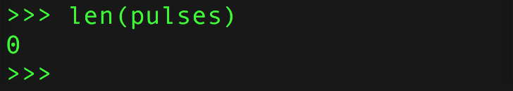
值為零表示傳感器尚未接收到脈沖。嘗試將遙控器對準傳感器,然后按一個按鈕。然后再次讀取脈沖長度:
下載:文件
復制代碼
len(pulses) len(pulses)

現在我們需要研究一些脈沖持續時間!首先,讓我們告訴脈沖類暫時停止監聽脈沖。這很有用,這樣您就可以在最后看到的脈沖上進行操作,而不會引起其他脈沖增加更多的噪聲或偽像:
下載:文件
復制代碼
pulses.pause() pulses.pause()
現在,通過讀取以下值來研究一些脈沖持續時間:如果脈沖對象是一個列表。例如,讀取前三個持續時間:
下載:文件
復制代碼
pulses[0]
pulses[1]
pulses[2] pulses[0]
pulses[1]
pulses[2]

每個持續時間是指脈沖處于特定邏輯電平的時間(以毫秒為單位)。第一個脈沖的最大值為65535,因為它代表傳感器等待脈沖開始的時間(即,處于默認高邏輯電平空閑狀態的時間)。就像上一頁中的Arduino代碼一樣,您可以忽略第一個值。
接下來的兩個值很有趣,下一個脈沖值顯示傳感器接收到的脈沖長約9毫秒(約9000)微秒)。然后,傳感器在約4毫秒內未收到脈沖。這對值代表一個脈沖和遙控信號的開始。最好看到?9ms開和?4m關的值,因為這是IR碼的常見序言或開始!
事實證明,這對脈沖在不同的遙控器之間如此常見,以至于其中許多可以用類似的代碼讀取。 Adafruit CircuitPython IRRemote庫是一個非常簡單的IR遠程控制解碼庫,可簡化許多脈沖和遠程解碼邏輯。讓我們使用此模塊簡化脈沖分析,首先將其導入,然后創建一個遠程解碼器:
下載:文件
復制代碼
import adafruit_irremote
decoder = adafruit_irremote.GenericDecode() import adafruit_irremote
decoder = adafruit_irremote.GenericDecode()

解碼器類使您可以輕松地等待并從遙控器上讀取脈沖列表。在使用前,請重新打開脈沖輸入(記住它當前已暫停)并清除其先前的輸入:
下載:文件
復制代碼
pulses.clear()
pulses.resume() pulses.clear()
pulses.resume()

現在,我們可以使用解碼器等待并返回脈沖了。運行此代碼,并注意REPL停止并等待進一步的輸入:
下載:文件
復制代碼
pulse = decoder.read_pulses(pulses) pulse = decoder.read_pulses(pulses)

將遙控器對準接收器,然后按一個按鈕。您應該看到REPL恢復正常運行。這意味著解碼器能夠檢測到紅外遠程信號并返回脈沖值的原始列表。

此脈沖列表是一個數組,其中包含來自接收器的每個高和低脈沖的長度(以微秒為單位)。例如,您可以使用標準陣列長度和打印操作來檢查檢測到多少脈沖變化并查看其長度:
下載:文件
復制代碼
len(pulse)
pulse len(pulse)
pulse

解碼器在內部執行的一項非常有用的操作是檢測并忽略噪聲或無關的脈沖寬度,例如在檢測到遙控器之前較長的起始脈沖寬度。這非常有用,因為它簡化了您的IR處理代碼-您可以集中精力查看“清理”的脈沖長度!
嘗試記錄第二個脈沖:
下載:文件
復制代碼
pulse2 = decoder.read_pulses(pulses) pulse2 = decoder.read_pulses(pulses)

記住 read_pulses 函數將等待檢測到遠程控制按下(或者如果以前發生過但未進行處理,它將代替它)。按下遙控器上的同一按鈕可產生與第一次按下類似的脈沖:

現在讓我們比較第一個和第二個脈沖列表,看它們是否匹配。一個簡單的比較可能是檢查每個列表中的每個值并驗證它們是否相同。讓我們用定義的簡單Python函數進行嘗試:
下載:文件
復制代碼
def simple_pulse_compare(pulse1, pulse2):
if len(pulse1) != len(pulse2):
return False
for i in range(len(pulse1)):
if pulse1[i] != pulse2[i]:
return False
return True
simple_pulse_compare(pulse, pulse2) def simple_pulse_compare(pulse1, pulse2):
if len(pulse1) != len(pulse2):
return False
for i in range(len(pulse1)):
if pulse1[i] != pulse2[i]:
return False
return True
simple_pulse_compare(pulse, pulse2)

哦,不,比較失敗并返回false!發生了什么,沒有按下相同的按鈕?事實證明,脈沖之間的時序可以以很小的方式變化。如果查看每個陣列的單個脈沖長度,您會發現它們很接近,但并不完全相同。如果您比較原始脈沖,則需要添加一個“模糊性”來比較接近但不完全相同的值。
讓我們創建一個新的模糊比較功能,該功能將檢查彼此接近的脈沖(例如,彼此相差20%以內):
下載:文件
復制代碼
def fuzzy_pulse_compare(pulse1, pulse2, fuzzyness=0.2):
if len(pulse1) != len(pulse2):
return False
for i in range(len(pulse1)):
threshold = int(pulse1[i] * fuzzyness)
if abs(pulse1[i] - pulse2[i]) 》 threshold:
return False
return True
fuzzy_pulse_compare(pulse, pulse2) def fuzzy_pulse_compare(pulse1, pulse2, fuzzyness=0.2):
if len(pulse1) != len(pulse2):
return False
for i in range(len(pulse1)):
threshold = int(pulse1[i] * fuzzyness)
if abs(pulse1[i] - pulse2[i]) 》 threshold:
return False
return True
fuzzy_pulse_compare(pulse, pulse2)

成功!使用模糊比較時,兩個脈沖似乎相同。默認情況下,如果脈沖之間的相距在20%之內,則比較將認為相同,但是您可以通過將Fuzzyness關鍵字設置為其他值來更改該模糊度。模糊度值是從0到1.0(或從0到0的百分比) 100%),其中脈沖必須在彼此定時的百分比之內。較低的值較為嚴格,需要更多類似的脈沖,而較高的值較不嚴格,可能會使噪聲或不正確的脈沖看起來相同。通常,除非您遇到更多有問題的IR信號,否則請堅持20%的模糊度。
讓我們通過編寫一個完整的程序來等待所有內容,等待上面的按鈕被按下,然后將它們綁在一起
您可以在程序中使用記錄的脈沖列表來記住先前記錄的脈沖,并與之比較新的脈沖。要檢測其他按鍵,只需按上述步驟進行記錄,并更新代碼中的脈沖列表。
將下面代碼頂部的脈沖列表更改為您記錄的值(只需從REPL復制并粘貼),然后將其保存為板上的 code.py :
下載IR CircuitPython示例
下載:Project Zip 或 IR.py | 在Github上查看
復制代碼
import board
import pulseio
import adafruit_irremote
IR_PIN = board.D2 # Pin connected to IR receiver.
# Expected pulse, pasted in from previous recording REPL session:
pulse = [9144, 4480, 602, 535, 600, 540, 595, 536, 599, 537, 600, 536,
596, 540, 595, 544, 591, 539, 596, 1668, 592, 1676, 593, 1667,
593, 1674, 596, 1670, 590, 1674, 595, 535, 590, 1673, 597, 541,
595, 536, 597, 538, 597, 538, 597, 1666, 594, 541, 594, 541, 594,
540, 595, 1668, 596, 1673, 592, 1668, 592, 1672, 601, 540, 592,
1669, 590, 1672, 598, 1667, 593]
print(’IR listener‘)
# Fuzzy pulse comparison function:
def fuzzy_pulse_compare(pulse1, pulse2, fuzzyness=0.2):
if len(pulse1) != len(pulse2):
return False
for i in range(len(pulse1)):
threshold = int(pulse1[i] * fuzzyness)
if abs(pulse1[i] - pulse2[i]) 》 threshold:
return False
return True
# Create pulse input and IR decoder.
pulses = pulseio.PulseIn(IR_PIN, maxlen=200, idle_state=True)
decoder = adafruit_irremote.GenericDecode()
pulses.clear()
pulses.resume()
# Loop waiting to receive pulses.
while True:
# Wait for a pulse to be detected.
detected = decoder.read_pulses(pulses)
print(’got a pulse.。。‘)
# Got a pulse, now compare.
if fuzzy_pulse_compare(pulse, detected):
print(’Received correct remote control press!‘)
現在按下時在遙控器按鈕上,您應該會看到一條消息打印在REPL上!這就是基本原始IR脈沖檢測以及與CircuitPython比較的全部內容!
此頁面上的代碼可以方便地進行基本或未知的遠程控制協議檢測。但是請注意,遙控器實際上是相當先進的,有時不能按您期望的方式工作-像多次按下按鈕一樣,實際上可能不會每次都發送完整的代碼,而遙控器可能會發送較短的重復代碼!這意味著此處顯示的基本原始IR檢測可能會失敗,因為它不希望看到重復代碼。
事實證明,常規的IR遠程檢測是如此先進,最好由單獨的庫處理,該庫可以解碼重復代碼等。對于CircuitPython,請從Chris Young那里檢查IRLibCP模塊,它具有更多功能完備的IR遠程解碼支持!
責任編輯:wv
-
紅外傳感器
+關注
關注
9文章
527瀏覽量
47801
發布評論請先 登錄
相關推薦
2025年紅外傳感器發展現狀:科技創新與市場擴展的交匯點
物聯網系統中常見的非接觸人體感應方案_紅外傳感器詳解
紅外傳感器和超聲波傳感器有什么區別
熱釋電紅外傳感器的基本特性和應用領域
紅外傳感器的主要優點有哪些
人體紅外傳感器輸出信號有哪些
人體紅外傳感器的數據屬于什么量
人體紅外傳感器的數據類型及工作原理
人體紅外傳感器的作用是什么
人體紅外傳感器能穿透玻璃嗎為什么
紅外傳感器技術深度解析:原理、分類、應用與選型策略

紅外傳感器電路圖 紅外傳感器的工作原理和應用


 工商網監
工商網監

評論